EasyManuals Logo

Behringer A500 User Manual

Behringer A500
12 pages
To Next Page IconTo Next Page
To Previous Page IconTo Previous Page
Page #9 background imageLoading...
Page #9 background image
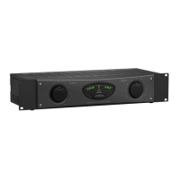
9 REFERENCE AMPLIFIER A500 User Manual
behringer.com
Audio connections4.3
Various cables are needed for different types of applications. The following
illustrations show the correct wiring. Always use high-grade cables.
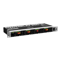
Fig. 4.1: XLR connections
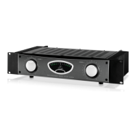
Fig. 4.2: ¼" TS connector
output
For unbalanced use, pin 1 and pin 3 have to be bridged
1 = ground/shield
2 = hot (+ve)
3 = cold (-ve)
input
12
3
1
2
3
Balanced use with XLR connectors
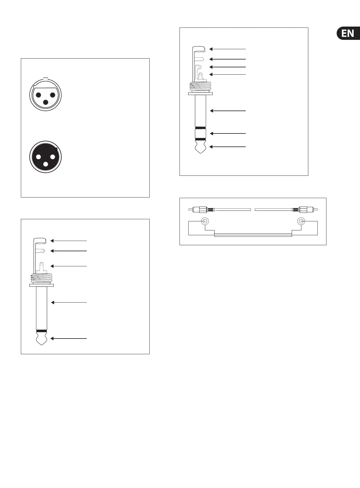
Fig. 4.3: ¼" TRS connector
Fig. 4.4: Unbalanced connection using a cinch cable
strain relief clamp
sleeve
ring
tip
sleeve
ground/shield
For connection of balanced and unbalanced plugs,
ring and sleeve have to be bridged at the stereo plug.
Balanced ¼" TRS connector
ring
cold (-ve)
tip
hot (+ve)
shield
sleevesleeve
tip tip

Other manuals for Behringer A500

Questions and Answers:

Question and Answer IconNeed help?

Do you have a question about the Behringer A500 and is the answer not in the manual?

Behringer A500 Specifications

General IconGeneral
Amplifier classA/B
Frequency range20 - 20000 Hz
Audio output channels2.0 channels
Peak power per channel300 W
Signal-to-Noise Ratio (SNR)100 dB
Total Harmonic Distortion (THD)0.01 %
RMS power output per channel (4 Ohm)185 W
RMS power output per channel (8 Ohm)125 W
Bridge-mode power output per channel (8 Ohm)375 W
XLR inYes
Line inputs (RCA)2
Speakers connectivity typeBinding post
PurposePerformance/stage
Cooling typePassive
Product colorBlack
Volume controlRotary
Connectivity technologyWired
LED indicatorsPower, Status
Weight and Dimensions IconWeight and Dimensions
Depth101.6 mm
Width257.5 mm
Height482.6 mm
Weight8800 g

Related product manuals