Do you have a question about the Behringer Denoiser SNR2000 and is the answer not in the manual?
Provides comprehensive guidelines for safe operation and maintenance of the unit.
Explains the philosophy behind Behringer product design and component selection.
Provides essential pre-operation checks, installation advice, and power connection guidelines.
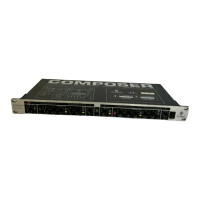
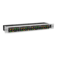
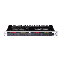
Details the layout and function of all controls and indicators on the front panel.
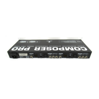
Describes the connectors and features available on the rear panel of the unit.
Explains how the Denoiser's filter section functions and its effects.
Explains how the Denoiser uses the masking effect to make noise inaudible.
Describes the function and operation of the dynamic low-pass filter.
Details the Transient Attack Control filter for fast signal response without distortion.
Explains how the sensitivity control affects the dynamic filter's opening threshold.
Describes the function of the CUT OFF control for setting the filter's lower frequency limit.
Provides guidance on setting the release time for the dynamic filter for optimal results.
Explains the AUTO switch function for automatic control of release time and cut off frequency.
Details the 8-digit LED meter indicating the filter's operating point and bandwidth.
Introduces the expander section and its role in reducing interference noise.
Describes the Interactive Ratio Control expander and its adaptive ratio characteristic.
Explains how to set the operating level for the expander section.
Details the function of the RELEASE control for the downward expander's time constant.
Describes the RATIO control for adjusting the expansion ratio and its effect on gate/expander function.
Explains the 8-LED gain reduction meter indicating the expander's activity.
Explains how to link channels for stereo tracking and control adjustments.
Provides recommended initial settings as a starting point for various applications.
Discusses specific applications of the Denoiser within studio environments.
Details how to use the Denoiser for noise reduction during audio playback.
Explains how to integrate the Denoiser into the recording path for enhanced noise reduction.
Describes methods for reducing noise on mixer subgroups, monitor, and effects buses.
Explains how to reduce noise generated by external effects units.
Details the use of the Denoiser to improve the quality of tape copies.
Explains how to reduce noise from digital instruments like synthesizers and samplers.
Describes how to reduce hum and noise in public address (PA) systems.
Explains how to use the Denoiser for noise reduction in Hi-Fi and video systems.
Explains the concept of audio dynamics and the dynamic range of various devices.
Discusses the function and application of compressors and limiters in audio processing.
Explains the principles of expanders and noise gates for reducing unwanted signals.
Details the concept of downward expansion for attenuating signals below a threshold.
Explains the origins of electrical and tape noise as physical phenomena.
Discusses compander systems and their limitations in noise reduction.
Explains the single-ended noise reduction approach used by the Denoiser.
Provides instructions for mounting the unit in a standard 19-inch equipment rack.
Details the servo-balanced inputs and outputs and connection guidelines.
Lists the specifications for the analog input connectors, type, impedance, and levels.
Lists the specifications for the analog output connectors, type, impedance, and levels.
Details overall system specifications including bandwidth, noise, THD, and crosstalk.
Lists the threshold, release, and ratio specifications for the expander section.
Lists the sensitivity, release, and cut-off specifications for the filter section.
Lists the specifications for function switches like IN/OUT, AUTO, and COUPLE.
Details the specifications for the LED gain reduction and filter bandwidth indicators.
Specifies mains voltages, fuse types, power consumption, and connection requirements.
Provides physical dimensions and weight specifications for the unit.
Outlines the process for registering the product to obtain extended warranty coverage.
Details the product's warranty coverage, terms, and limitations.
Explains the procedure for obtaining a return authorization number for warranty service.
Specifies the regulations and conditions applicable to warranty services and claims.
Clarifies that the warranty is exclusive to the original buyer and not transferable.
Defines the limits of liability for damages and claims against the manufacturer.
Addresses statutory buyer rights and national law in relation to the warranty.
| Channels | 2 |
|---|---|
| Inputs | 2 x XLR, 2 x 1/4" TRS |
| Outputs | 2 x XLR, 2 x 1/4" TRS |
| Signal-to-Noise Ratio | >100 dB |
| THD | <0.05% |
| Dynamic Range | >100 dB |
| Frequency Response | 20 Hz to 20 kHz |