10
ULTRA-Q PRO PEQ2200
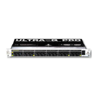
4.1 The front panel control elements
Fig. 4.2: Control elements on the front panel
1
The AUDIO IN/OUT switch is used to enable/disable the entire equalizer section in the audio path. The
switch uses a relay-controlled hard-bypass function, i.e. as long as it is not pressed or if the unit is
switched off, the inputs are directly connected to the outputs. The AUDIO IN/OUT switch allows for A/B
comparisons between the processed and unprocessed signals.
2
Use the I/O METER IN/OUT switch to select the input source. Press it to display the input level.
3
The level meters are used to monitor the signal levels, so as to avoid distortion caused by overloading.
Depending on the setting of the I/O METER IN/OUT switch, the display shows the input or output level
(switch pressed). The upper red LED lights up as soon as a level of about +18 dBu (i.e. 3 dB below
clipping) is reached.
+ Please note that extreme boost settings in combination with a high input level can overload
the unit. In such a case, the input level must be reduced with the INPUT control.
4
The INPUT control determines the input level applied to the device and can be set within a range from
-15 to +15 dB.
5
The LOW CUT control adjusts the lower cutoff frequency of the ULTRA-Q PRO. The high-pass filter can
be tuned from 10 to 400 Hz. In the 10 Hz position the signal passes unchanged.
6
The HIGH CUT control adjusts the upper cutoff frequency of the ULTRA-Q PRO. The low-pass filter can
be tuned from 2.5 to 30 kHz. In the 30 kHz position the signal passes unchanged.
7
The FREQUENCY control selects the filters center frequency, which can be freely chosen from within
the frequency range of the associated band.
8
The BANDWIDTH control determines the slope or quality of the filter. Settings from 0.03 (Q=43) to 2
octaves (Q=0,67) are possible.
9
The LEVEL control determines the amount of level boost/cut. The setting range is from -15 to +15 dB.
10
The individual IN/OUT switches allow for enabling/disabling specific bands in the audio path.
4. CONTROLS