ULTRA-G GI100
4
1. CONTROLS
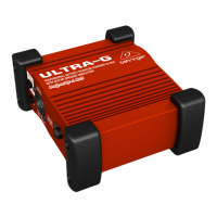
Fig. 1.1: The GI100s front and back panels
1
The VIRTUAL 4x12" CAB speaker simulation can be switched on and off
with the SIMULATOR ON/OFF switch.
2
When activated, the GND LIFT breaks the ground connection between
input and output. Depending on the grounding of the connected equip-
ment, this can eliminate hum or ground loops.
3
OUTPUT TO MIXER is the GI100s balanced, mic level output. Use a
high-quality, balanced XLR (microphone) cable to connect the ULTRA-G
to a console.
+ You should never connect pins 2 or 3 with pin 1 or remove the
shield from pin 1. Otherwise, it will not be possible to operate the
unit with phantom power.
4
BATTERY COMPARTMENT. To install or replace the 9V battery, remove
the screw and lift the lid.
5
The CLIP LED lights up when the input signal level is too high.
6
The two -20 dB PAD switches noticeably increase the operating range of
the ULTRA-G, allowing it to accept anything from the low-level signal of
a high-impedance microphone or guitar to the loudspeaker output of a
guitar amp. These switches have repeatedly proven themselves in the
BEHRINGER ULTRA-DI DI100. Pressing both switches results in a gain
reduction of 40 dB.
1. CONTROLS
 Loading...