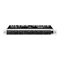
ULTRAVOICE VX2000
5
+ The following users manual is intended to familiarize
you with the units control elements, so that you can
master all the functions. After having thoroughly read
the users manual, store it at a safe place for future
reference.
1.1 Before you get started
The ULTRAVOICE was carefully packed at the assembly plant
to assure secure transport. Should the condition of the cardboard
box suggest that damage may have taken place, please inspect
the unit immediately and look for physical indications of damage.
+ Damaged units should NEVER be sent directly to us.
Please inform the dealer from whom you acquired the
unit immediately as well as the transportation company
from which you took delivery of the unit. Otherwise, all
claims for replacement/repair may be rendered invalid.
1.1.1 Initial operation
Please make sure the unit is provided with sufficient ventilation,
and never place the ULTRAVOICE on top of an amplifier or in the
vicinity of a heater to avoid the risk of overheating.
+ Before plugging the unit into a power socket, please
make sure you have selected the correct voltage:
The fuse compartment near the power plug socket contains
three triangular markings. Two of these triangles are opposite
one another. The voltage indicated adjacent to these markings is
the voltage to which your unit has been set up, and can be altered
by rotating the fuse compartment by 180°. ATTENTION: This
does not apply to export models that were for example
manufactured only for use with 120 V!
+ If you alter the units voltage, you must change the fuses
accordingly. The correct value of the fuses needed can
be found in the chapter TECHNICAL DATA.
+ Faulty fuses must be replaced with fuses of appropriate
rating without exception! The correct value of the fuses
needed can be found in the chapter TECHNICAL DATA.
Power is delivered via the cable enclosed with the unit. All
requiered safety precautions have been adhered to.
+ Please make sure that the unit is grounded at all times.
For your own protection, you should never tamper with
the grounding of the cable or the unit itself.
1.1.2 Warranty
Please take a few minutes and send us the completely filled
out warranty card within 14 days of the date of purchase. You
may also register online at www.behringer.com. The serial number
needed for the registration is located at the top of the unit. Failure
to register your product may void future warranty claims.
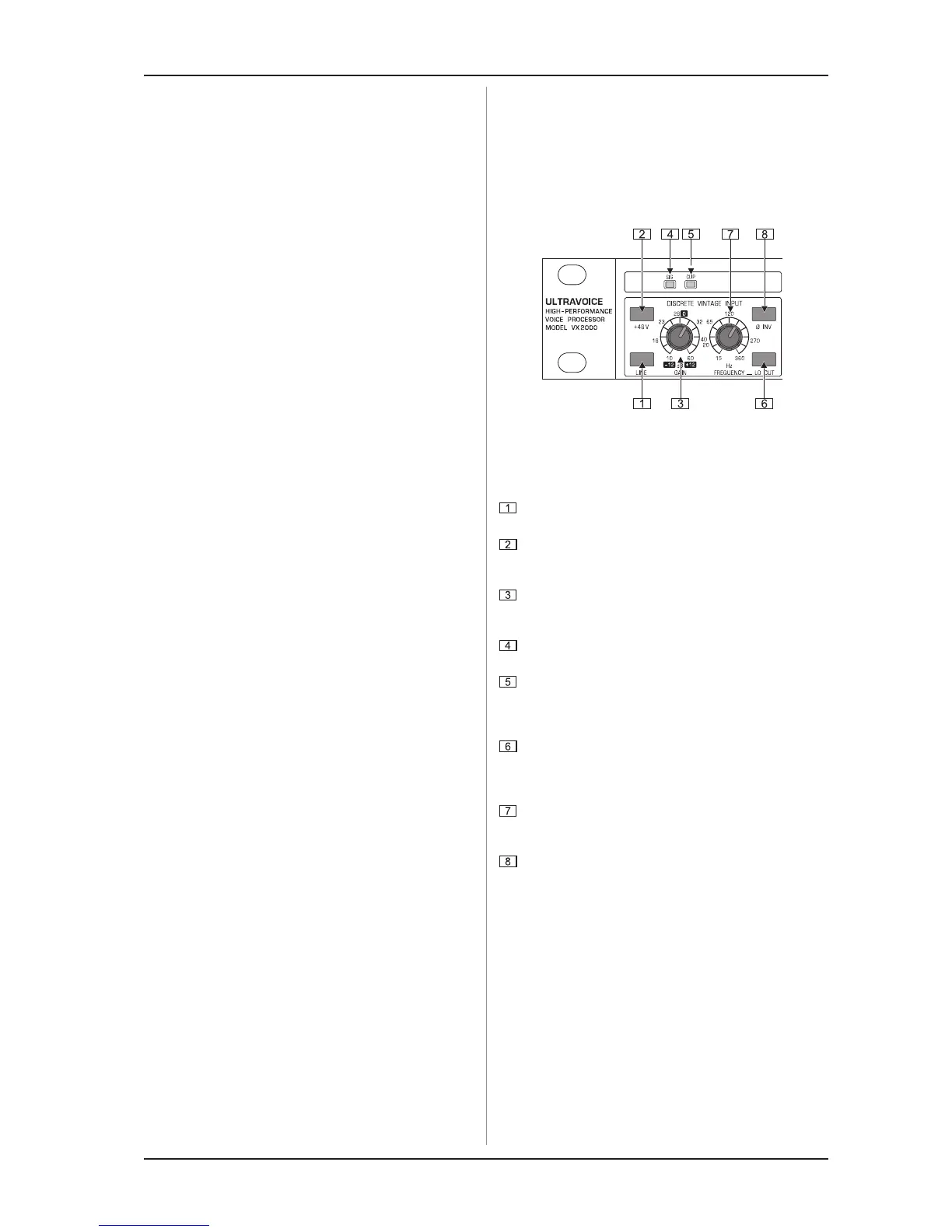
2. CONTROL ELEMENTS
This chapter contains descriptions of various control elements
of your ULTRAVOICE. All controls and connections are discussed
in detail. Additionally, useful advice about their possible
applications is also given.
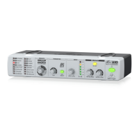
2.1 Discrete vintage input stage
Fig. 2.1: Discrete vintage input stage
This section of your ULTRAVOICE contains a preamplifier
that allows you to determine the input level of mic or line
signals.
Use the LINE switch to select the type of input signal used
(in = LINE; out = MIC).
Press the +48V switch to provide condenser microphones
with the necessary phantom power supply voltage. Dynamic
microphones need no additional supply voltage.
The GAIN control adjusts the input level. The scale ranging
from -12 to +12 dB refers to the LINE input, the 10 through
60 dB scale to the MIC input.
The SIG LED above the GAIN control lights up as soon as
a signal is present at the input.
Make sure that the CLIP LED lights up only occasionally
during loud passages. If it lights permanently or you can
hear audible distortion, you should reduce the input level
with the GAIN control.
The ULTRAVOICE has a low-cut filter that eliminates low-
frequency interference from your microphone signals. Use
the LO CUT switch to activate this function. The filter has a
slope of 12 dB/oct.
With the FREQUENCY control you can determine the
frequency below which interference signals are suppressed
(15 Hz through 360 Hz).
The Ø INV switch inverts the signal phase by 180°. Use this
function in a multi-microphone set-up if you detect phase
cancellations in specific frequency bands.
2. CONTROL ELEMENTS