ULTRAVOICE VX2000
6
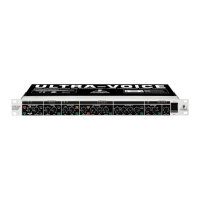
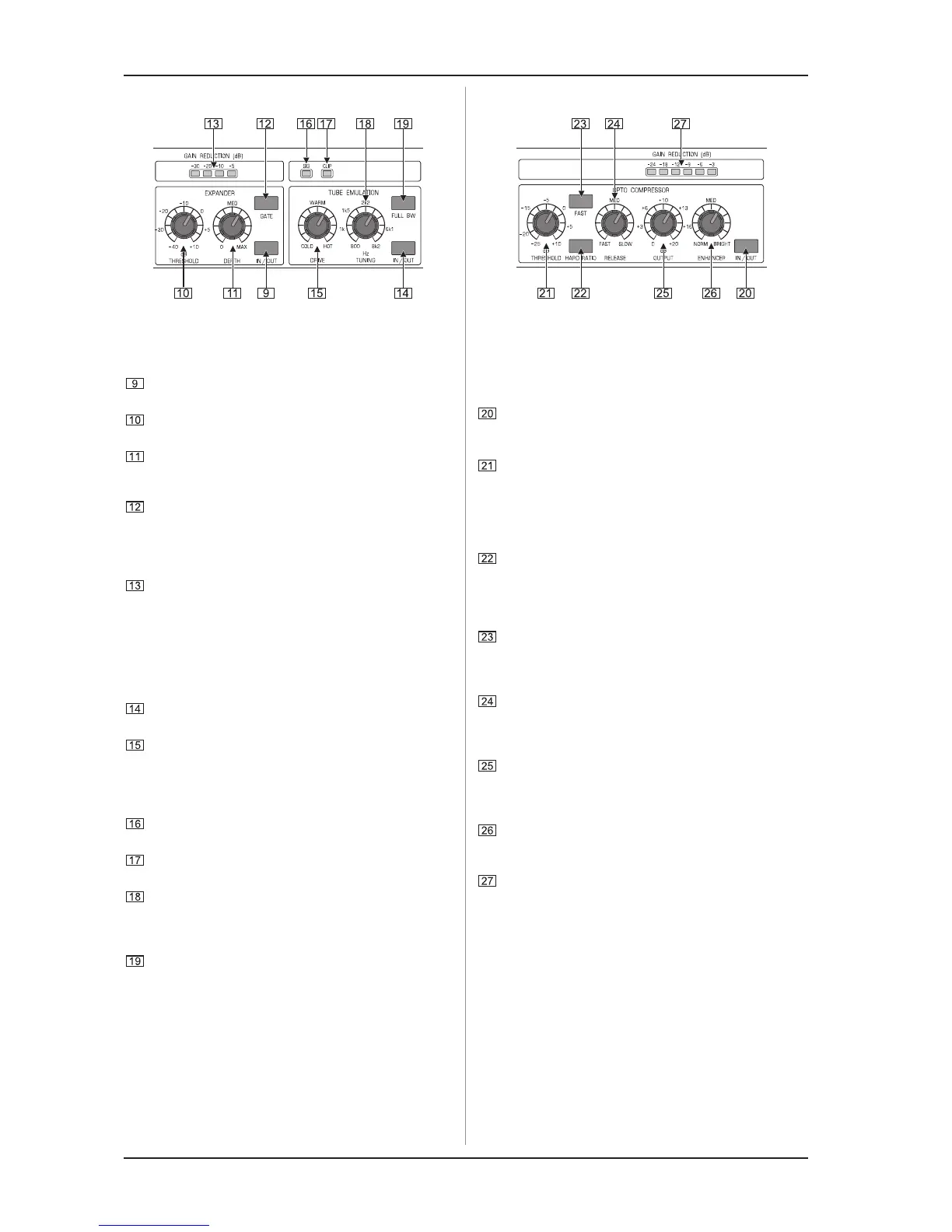
2.2 Expander and tube emulation
Fig. 2.2: Expander and tube emulation
The expander reduces the signal level during soft passages,
so as to eliminate interference such as tape hiss or crosstalk.
Use the IN/OUT switch to activate or bypass the expander
in the signal path.
The THRESHOLD control adjusts the level above which
the expander comes in.
The DEPTH control determines the degree of signal
reduction. The higher this value, the more signal reduction
is applied.
Press the GATE switch to make the expander work like a
noise gate, which not only reduces the signal level during
soft passages but cuts it completely. The gate function
should therefore be applied to single signals only, so as to
avoid affecting the entire recording.
The four GAIN REDUCTION LEDs signal the degree of
level reduction applied from -5 through -30 dB.
The tube emulation function allows you to add a subtle
distortion or tape saturation effect to vocals. Known from
analog tape recorders and tube amplifiers this effect adds
some upper harmonics to the signal and hence enhances it
in the treble range.
Use the IN/OUT switch to enable/disable the tube emulation
function.
The DRIVE control governs the intensity of the saturation
effect. The more you turn it to the right (HOT), the more
pronounced the effect will be. The portion of upper harmonics
produced also depends on the input level adjusted in the
discrete vintage input stage.
The SIG LED lights up when the tube emulation function
has been switched on.
To avoid internal distortion, the CLIP LED should never light
up all the time, but only briefly during very loud passages.
The TUNING control determines the frequency range to be
processed with the saturation function. As all other ranges
remain unaffected, you can apply this effect to specific
frequency ranges.
Press the FULL BW switch to process the entire frequency
spectrum. In this case, the TUNING control is inoperative.
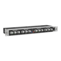
2.3 Opto compressor
Fig. 2.3: Opto compressor
The opto compressor reduces the dynamics of the input
signal, i.e. the difference between soft and loud passages
becomes smaller. Level peaks exceeding a specific threshold
will be cut back to smooth out the overall sound image.
The IN/OUT switch activates the compressor. Use this
switch to make a direct A/B comparison between
compressed and uncompressed signals.
The THRESHOLD control determines the input level above
which the opto compressor starts processing the input signal.
Only if the adjusted threshold is exceeded will the
compressor be activated. The dynamics of soft passages
below that level remain unprocessed. The lower the
threshold you choose, the more compression will be applied.
The HARD RATIO switch sets the signal reduction to
maximum, producing a highly compressed sound whose
dynamics are completely leveled out. Dont use this function
if you want to preserve the natural dynamics of the input
signal.
Press the FAST switch if you want the opto compressor to
react quickly, once the threshold has been surpassed. In
this case, the overall signal will be considerably more
compressed, producing a very powerful sound.
Use the RELEASE control to adjust the compressor release
time, which is the time that starts when the signal has fallen
back below the threshold. The longer the release time, the
more compressedand balancedthe sound image will be.
The OUTPUT control governs the output level of the
compressed signal. As compression reduces the signal
level, you can use this control to make up for the level
reduction.
Compression may suppress specific frequency ranges. The
built-in ENHANCER allows you to make up for this and round
out the sound image by giving it new brilliance.
The six GAIN REDUCTION LEDs display the degree of
compression ranging from -3 through -24 dB.
2. CONTROL ELEMENTS