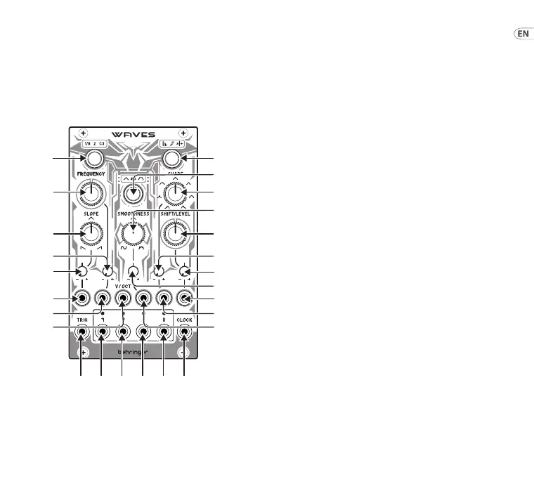
(EN) Controls
1. FREQUENCY RANGE – use this button to select the
central frequency range of the control (7):
Green – ⁄ Hz
Orange – 2 Hz
Red – 131 Hz
The LED surround will light in the relevant color.
2. RELATIONSHIP – use this button to set the relationship
between the four CV outputs (22 – 25): O – the four
outputs produce dierent waveforms, with control
16 acting as an attenuverter on Output 1.
• Output 1 – Triangle wave, aected by all controls
• Output 2 – Triangle wave, aected by all controls
• Output 3 – Pulse Wave, with PWM coming from
the SLOPE control
• Output 4 – Square wave
Green – Control 16 sets a crossfade between the
four outputs.
Orange – Control 16 osets the peaks of the outputs.
Red – Control 16 adjusts the ratios of the outputs.
At 12 o’clock all follow the frequency set by control 7,
turning clockwise (CW) increases the frequencies of
outputs 23 – 25, turning counter-clockwise (CCW)
decreases them.
The LED surround will light in the relevant color.
3. MODE – use this button to select the working mode:
Green – unipolar one-shot AD envelope,
with a range of 0 V to +8 V.
Orange – bipolar cyclic LFO/VCO, with a range of
-5 V to +5 V.
WAVES Controls
(1)
(7) (13)
(10)
(16)(4)
(20) (22) (23) (24) (25) (21)
(18)
(17)
(11)
(14)
(
5)
6)
8)
9)
15Quick Start Guide14 WAVES