Quick Start Guide 9
The section also has dedicated level knobs for the headphone outputs (located on the underside of the top edge) and the monitor outputs (which default to
Aux output 7/8 on the rear panel). Engaging the DIM button reduces the monitor volume, and the MONO button sums the monitor signal to mono.
The talkback mic level can be adjusted via TALK LEVEL knob, and TALK A and B buttons send the talkback signal to dierent destinations. Either Channel 40 or
Aux 8 can be used as input for the talkback channel.
Press the VIEW button to control the monitor settings, adjust the amount of Dim attenuation, select routing for the talkback mic, and other parameters.
Fader Sections
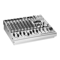
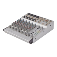
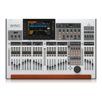
The WING has 3 fader sections that each have their own associated bank buttons. The group of 12 faders to the left side of the console are labeled mostly for input
channels, the group of 8 faders in the center typically control buses and DCAs, and the small group of 4 faders to the right are meant for main or matrix outputs.
However, there are no restrictions with how the fader banks can be congured. To access the fader bank conguration, press and hold the VIEW button for one of
the fader sections.
Input channels Bus/DCA/Matrix Main/Matrix
Layer/Bank buttons
Selecting dierent fader banks will instantly bring a new set of channels to the
associated fader section, including the scribble strip names/icons, and the
motorized faders will jump to their correct positioning. If a particular bank does
not t on the available physical faders in a section (for example, Bus Masters), the
shift arrows will scroll in blocks of 4 to access the remaining channels. Each fader
section also has 2 user-dened banks that can contain a variety of channels.
For monitor mixing, a very convenient feature called Sends on Faders is available
to quickly adjust the channel send levels to a particular bus.
• Press the SOF FLIP button to activate Sends on Faders. The MUTE
buttons on all sends (input channel fader strips) are active by default
to protect buses in subgroup mode.
• Make sure the BUS MASTERS button is lit in the bus fader section,
then press one of the SELECT buttons to identify the bus to which
channel signals will be sent.
• Raise the input channel faders for each of the channels that should
be sent to that bus, navigating through the dierent input banks
if necessary.
Remember to disengage the SOF FLIP button when you want to return to
normal mixing.