Do you have a question about the BEKA BA307E and is the answer not in the manual?
Details the functions of the four front panel push-buttons for control and calibration.
Details the EC-Type Examination Certificate and compliance with ATEX Directive for Group II equipment.
Specifies ATEX zones (0, 1, 2), gas groups (propane, ethylene, hydrogen), and temperature ratings.
Mentions 'X' suffix for special conditions in IIIC conductive dust atmospheres.
Lists input safety parameters (Ui, Ii, Pi) and maximum capacitance/inductance for the 4/20mA loop.
Describes the information found on the certification label affixed to the instrument.
Details connecting indicators in series with intrinsically safe 4/20mA current loops and design requirements.
Discusses using an intrinsically safe interface for remote display within a hazardous area.
Discusses indicator placement, operating temperature range, and IP66 front panel protection.
States compliance with the European EMC Directive and recommends screened twisted pair wiring.
Provides detailed steps for cutting apertures, fitting panel mounting clamps, and connecting wiring.
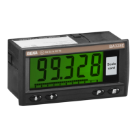
Explains how to view and change the scale card showing units of measurement.
Summarizes main configuration functions with cross-references for detailed descriptions.
Defines the relationship between 4/20mA input and indicator display (Std, root, Lin).
Sets the resolution of the least significant display digit (1, 2, 5, or 10).
Allows positioning of a dummy decimal point on the display.
Explains calibrating zero and span using an external calibrated current source.
Details calibrating zero and span using the indicator's internal references.
Configures bargraph display (start, finish, justification) for models with bargraphs.
Configures the P button to show input current in mA or as a percentage of span.
Enables setting the display to zero when the E button is operated in display mode.
Sets a four-digit code to access the configuration menu, defaulting to 0000.
Resets the indicator or lineariser to factory default configurations.
Describes how the indicator displays under/over-range conditions with decimal points flashing.
Details direct calibration of the lineariser using an external current source for traceability.
Describes lineariser calibration using the indicator's internal reference without external source.
Explains the 'Fail' error message for incorrect break-point positioning or out-of-range values.
Describes how under/over-range is indicated when using the lineariser.
Lists default break-point configurations (4mA, 20mA) after a reset.
Provides a table for troubleshooting symptoms, causes, and solutions during initial setup.
Outlines procedures for diagnosing faults after the instrument has been installed and is operational.
Advises on returning instruments for repair and avoiding component-level repairs.
Recommends regular checks of mechanical condition and electrical calibration annually.
Instructions for returning instruments within the guarantee period.
Encourages customer feedback and suggestions for improvement.
Explains how to view and fit scale cards for units of measurement.
Describes the tag or application information printed on the rear panel.
Covers factory-fitted dual solid state alarm outputs, high/low configuration, and setpoint adjustment.
Explains connecting the backlight in series with the 4/20mA input, increasing voltage drop.
Details powering the backlight from a separate safe area supply for brighter illumination.
Details ATEX certification permitting installation in combustible dust atmospheres.
Specifies ATEX dust zones (20, 21, 22), subdivisions (IIIA, IIIB, IIIC), and ignition temperatures.
Discusses maintenance considerations related to dust protection and IP sealing.
Outlines special conditions for safe use in IIIC conductive dust atmospheres, requiring IP6X terminal protection.
Describes the IECEx global certification scheme for explosion protected products.
Lists the IECEx Certificate of Conformity number and certification codes for intrinsic safety.
States that IECEx and ATEX installation requirements are identical, referencing EN 60079-14.
Details special conditions for safe use in IIIC dust atmospheres for IECEx certification.
Mentions FM and CFM intrinsic safety and nonincendive approvals and project identification numbers.
Details intrinsic safety approval to FM Class 3610 for Division 1 & 2 hazardous locations.
Covers FM Class 3611 nonincendive approval for Division 2 hazardous locations.
| IP Rating | IP66 |
|---|---|
| Display Type | LCD |
| Touch Screen | No |
| Input Voltage | 24V DC |
| Backlight | LED |
| Mounting | Panel mount |
| Input | 4-20 mA |