5
3.4 4/20mA input
The input safety parameters for the 4/20mA input,
terminals 1 and 3 are:
Ui = 30V dc
Ii = 200mA
Pi = 0.84W
The maximum equivalent capacitance and
inductance between the two 4/20mA input
terminals 1 and 3 is:
Ci = 13nF
Li = 8µH (Effectively 0)
The maximum permitted loop cable parameters
can be calculated by adding these figures to Ci
and Li of other instruments in the loop and
subtracting the totals from the maximum cable
capacitance Co and cable inductance Lo permitted
for the Zener barrier or galvanic isolator powering
the loop.
Although the indicators do not themselves comply
with the requirements for simple apparatus, the
EC-Type Examination Certificate states that for
intrinsic safety considerations, under fault
conditions the output voltage, current and power at
terminals 1 & 3 will not exceed those specified by
clause 5.7 of EN 60079-11 for simple apparatus.
This simplifies the application and intrinsic safety
documentation for a loop into which an indicator is
connected. Apart from Ci, the effect of the
indicator’s may be ignored when assessing the
loop safety.
3.5 Certification label information
The certification label is fitted in a recess on the
top outer surface of the instrument enclosure. It
shows the ATEX certification information,
instrument serial number, year of manufacture plus
BEKA associates' name and location. Non
European certification information may also be
included, a typical label is shown below.
BA307E certification label
4. SYSTEM DESIGN FOR GAS HAZARDOUS
AREAS
4.1 Transmitter loops
All indicator models may be connected in series
with almost any intrinsically safe 4/20mA current
loop and calibrated to display the measured
variable or control signal in engineering units.
There are three basic design requirements:
1. The intrinsic safety output parameters of the
4/20mA loop, which are defined by the Zener
barrier or galvanic isolator powering the loop,
must be equal to or less than:
Uo = 30V dc
Io = 200mA
Po = 0.84W
2. The maximum permitted cable capacitance
of the loop must be reduced by 13nF. The
maximum permitted cable inductance is not
reduced by the inclusion of an indicator.
3. The loop must be able to tolerate the
additional 1.2V required to operate the
indicator. When fitted with an optional
backlight this increases to 5.0V if the
backlight is loop powered. See 9.4.1
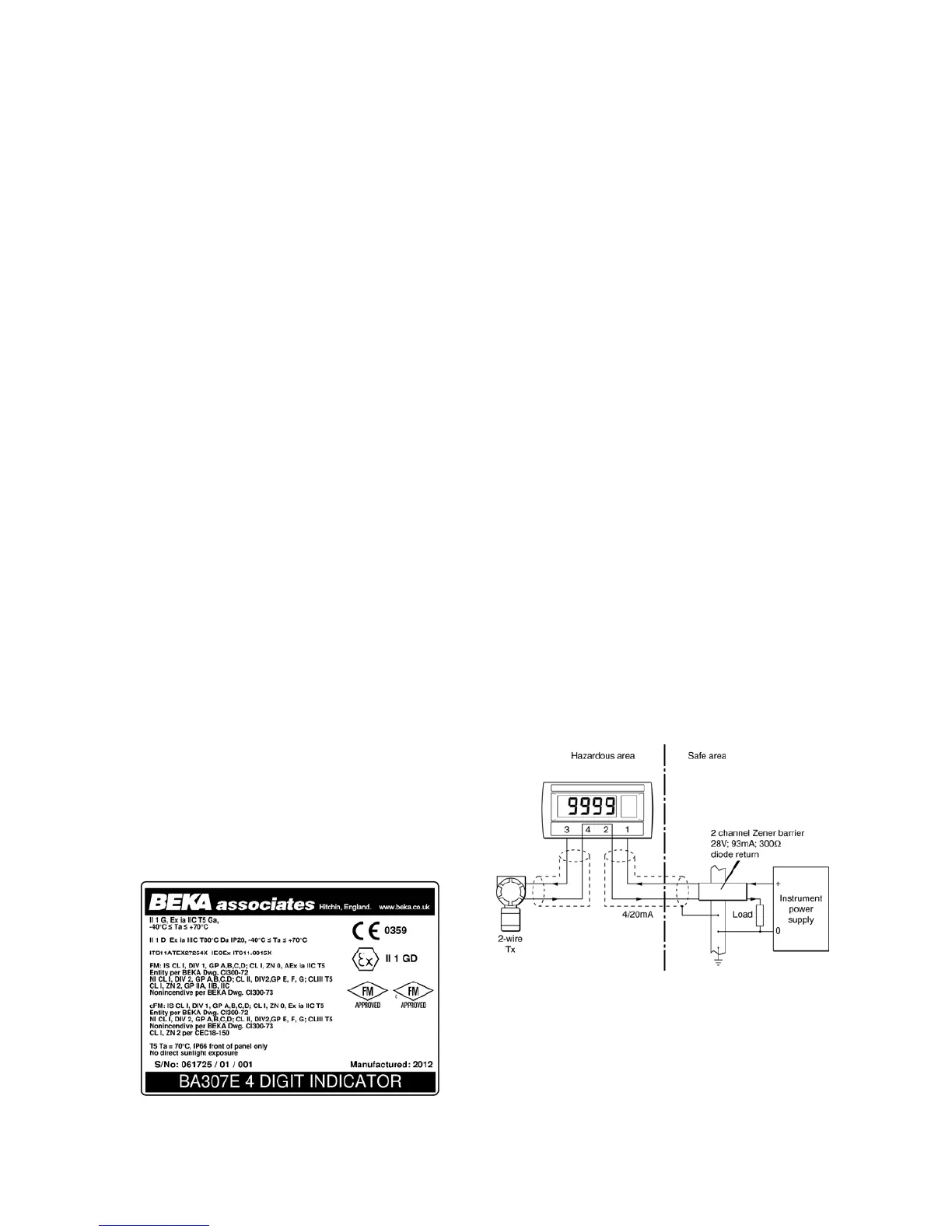
Figs 2a and 2b illustrate typical applications in
which an indicator is connected in series with a
2-wire transmitter powered by a Zener barrier and
alternatively by a galvanic isolator.
Fig 2a Loop powered by a Zener barrier