4
2.1 Controls
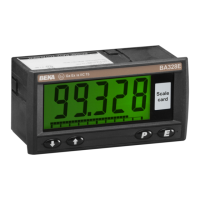
The indicators are controlled and calibrated via
four front panel push-buttons located below the
display. In the display mode i.e. when the
indicator is displaying a process variable, these
push-buttons have the following functions:
P While this button is pushed the
indicator will display the input current in
mA, or as a percentage of the
instrument span depending upon how
the indicator has been conditioned.
When the button is released the normal
display in engineering units will return.
The function of this push-button is
modified when optional alarms are
fitted to the indicator.
▼ While this button is pushed the
indicator will display the numerical
value and analogue bargraph* the
indicator has been calibrated to display
with a 4mA
Φ
input. When released the
normal display in engineering units will
return.
▲ While this button is pushed the
indicator will display the numerical
value and analogue bargraph* the
indicator has been calibrated to display
with a 20mA
Φ
input. When released
the normal display in engineering units
will return.
E No function in the display mode unless
the tare function is being used.
P + ▼ Firmware number followed by version.
P + ▲ Direct access to the alarm setpoints
when optional alarms are fitted to the
indicator and the ‘ACSP’ access
setpoints in display mode function has
been enabled.
P + E Access to configuration menu via
optional security code.
Note: * BA327E and BA328E only
Φ
If the indicator has been calibrated
using the CAL function, calibration
points may not be 4 and 20mA.
3. INTRINSIC SAFETY CERTIFICATION
All models have ATEX and IECEx gas and dust
certification. This section of the instruction manual
describes ATEX gas certification. ATEX dust and
IECEx approvals are described in Appendixes 1
and 2.
3.1 ATEX gas certification
All the models have been issued with a common
EC-Type Examination Certificate number
ITS11ATEX27254X by Notified Body Intertek
Testing and Certification Ltd. This confirms
compliance with harmonised European standards
and it has been used to confirm compliance with
the European ATEX Directive for Group II,
Category 1G equipment, Ex ia IIC T5 Ta = -40 to
+70ºC. The indicators bear the community mark
and subject to local codes of practice may be
installed in any of the European Economic Area
(EEA) member countries. ATEX certificates are
also acceptable for installations in Switzerland.
This section of the instruction manual describes
ATEX installations in explosive gas atmospheres
conforming with EN60079-14 Electrical
Installations design, selection and erection. When
designing systems for installation outside the UK
the local Code of Practice should be consulted.
3.2 Zones, gas groups and T rating
The indicators have been certified Ex ia IIC T5.
When connected to a suitable system the indicator
may be installed in:
Zone 0 explosive gas air mixture
continuously present.
Zone 1 explosive gas air mixture likely
to occur in normal operation.
Zone 2 explosive gas air mixture not
likely to occur, and if it does
will only exist for a short time.
Be used with gases in groups:
Group A propane
Group B ethylene
Group C hydrogen
Having a temperature classification of:
T1 450
o
C
T2 300
o
C
T3 200
o
C
T4 135
o
C
T5 100
o
C
At ambient temperatures between -40 and +70
o
C.
This allows the indicators to be installed in all gas
Zones and to be used with most common industrial
gases.
3.3 Special conditions for safe use
The ATEX certificate has an ‘X’ suffix indicating
that special conditions apply for installations in IIIC
conductive dust atmospheres. No special
conditions apply to installations in gas or in IIIA
and IIIB dust atmospheres. See Appendix 1 for
information about use in dust atmospheres.