2
WIRING DIAGRAMS
CQ..24V, CQB24-3, CQB24-SR (-L) (-R)
24 VAC Transformer
Blk Common
Wht +
Red +
Line
Volts
A
2 3 18
Functions A
100%
0%
Notes:
On/Off, CQB24-3 Floating Point, CQB24-3
Line
Volts
Control Signal
VDC/mA
Blk Common
Red + Hot
Wht Y
1
Input, 2 to 10V
500
2 3 185 7
2 VDC Open
10 VDC
Close
24 VAC Transformer
Line
olts
Control Signal
VDC/mA
Blk Common
Red + Hot
Wht Y
1
Input, 2 to 10V
500
2 3 185 7
2 VDC
Close
10 VDC
Open
Proportional, CQB24-SR-L Proportional, CQB24-SR-R
CQ..110-240V, CQBUP-3
110 to 230 VAC
Blu Common
Wht
+
Brn +
Line
olts
A
2 18
AFunctions
100%
0%
Blu Common
Brn +
Wht +
Line
Volts
A
B
Functions
100%
0%
A
B
On/Off, CQBUP-3 Floating Point, CQBUP-3
Meets cULus requirements without the need of an
electrical ground connection
2
Actuators may be connected in parallel. Power
consumption and input impedance must be
observed.
3
Actuators may also be powered by 24 VDC.
5
Only connect common to neg. (-) leg of control
circuits.
7
A 500 Ω (ZG-R01) converts the 4 to 20 mA control
signal to 2 to 10 VDC.
18
Actuators with plenum rated cable do not have
numbers on wires; use color codes instead.
BLK
Black
Negro
Noir
Preto
RED
Red
Rojo
Rouge
Vermelho
WHT
White
Blanco
Blanc
Branco
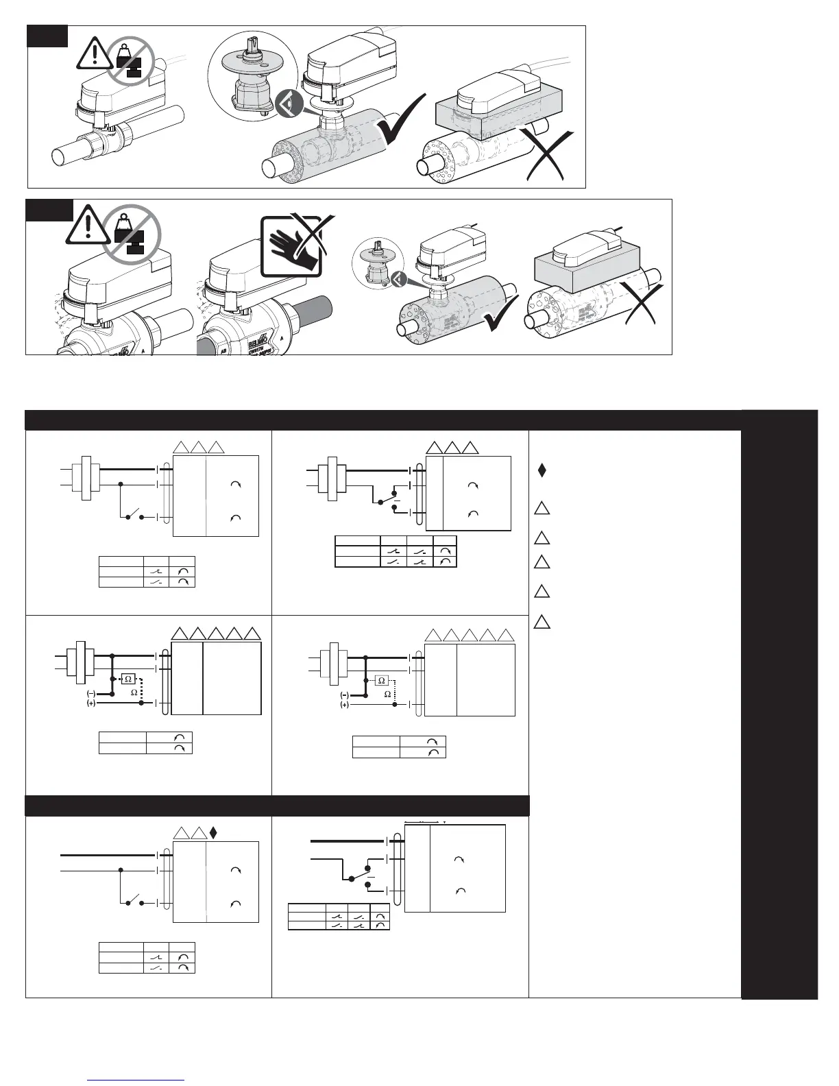
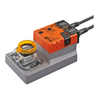
kg
>122°F
PIQCV
!
kg
QCV
Functions
100%
0%
A
B
1 Common
2 +
3 +
Line
Volts
A
B
2 3 18