800-543-9038 USA 866-805-7089 CANADA 203-791-8396 LATIN AMERICA / CARIBBEAN
13
N40067 - 7/11 - Subject to change. © Belimo Aircontrols (USA), Inc.
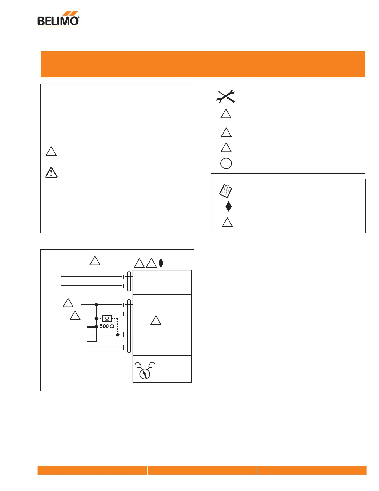
Wiring for Damper Actuators and Control Valves
Proportional, Non-Spring Return, 100 to 240V
15
Actuators: LMX120-SR AMX120-SR ARX120-SR
NMX120-SR LRX120-SR
7
15
LMB(X), NMB(X), AMB(X), GMB(X), LRB(X), and
ARB(X) can be supplied with either 120 VAC or 230 VAC.
Only connect common to neg. (–) leg of control circuits.
6
INSTALLATION NOTES
Meets cULus requirements without the need of an
electrical ground connection.
A 500 Ω resistor converts the 4 to 20 mA control
signal to 2 to 10 VDC.
APPLICATION NOTES
Equipment damage!
Actuators may be connected in parallel. Power
consumption and input impedance must be observed.
2
CAUTION
Indicates a potentially hazardous situation which, if not avoided,
may result in minor or moderate injury. It may also be used to
alert against unsafe practices.
Warnings and Cautions appear at appropriate sections throughout
this manual. Read these carefully.
Hazard Identification
2
Wht (1) Neutral
Blk (2) Hot +
N L1
H L2
6
Blk (1) Common
Red (2) Hot +
Wht (3) Y Input,
2 to 10V
Control Signal
2 to 10 VDC
Feedback Signal
Org (5) U Output, 2 to 10V
(–)
(+)
(–)
(+)
10
100 to 240 VAC
Cable 2Cable 1
5
19
All 120 VAC and 230 VAC actuators use appliance rated
cables.
19
7
VDC/mA
Actuators with appliance cables are numbered.
A
W365_11
WARNING
Live Electrical Components!
During installation, testing, servicing and troubleshooting of this
product, it may be necessary to work with live electrical
components. Have a qualified licensed electrician or other
individual who has been properly trained in handling live electrical
components perform these tasks. Failure to follow all electrical
safety precautions when exposed to live electrical components
could result in death or serious injury.