800-543-9038 USA 866-805-7089 CANADA 203-791-8396 LATIN AMERICA / CARIBBEAN
16
N40067 - 7/11 - Subject to change. © Belimo Aircontrols (USA), Inc.
Wiring for Damper Actuators and Control Valves
Proportional, Spring Return, 24V, 2 to 10 VDC (or 4 to 20 mA)
Control Signal or Three-Position On/Off Control
5
7
3
Equipment damage!
Actuators may be connected in parallel. Power consumption
and input impedance must be observed.
2
CAUTION
Indicates a potentially hazardous situation which, if not avoided,
may result in minor or moderate injury. It may also be used to
alert against unsafe practices.
Warnings and Cautions appear at appropriate sections throughout
this manual. Read these carefully.
Hazard Identification
INSTALLATION NOTES
26
26
31
31
32
32
W176
Three-Position Control with a SPDT Switch or Two Contact
Closures (e.g. fan, cooling Y)
W176
Min-Position with Full Open Override (with a single
contact closure)
Actuators may also be powered by 24 VDC.
Actuators with plenum rated cable do not have numbers on
wires; use color codes instead. Actuators with appliance
cables are numbered.
A 500 Ω resister converts the 4 to 20 mA control signal to
2 to 10 VDC.
Min-position is adjustable from 0 to 100% with a
potentiometer on the actuator cover.
For three-position control set direction of rotation to CW (default).
Switch A, actuator spring returns when open (e.g., fan interlock).
5
3
5
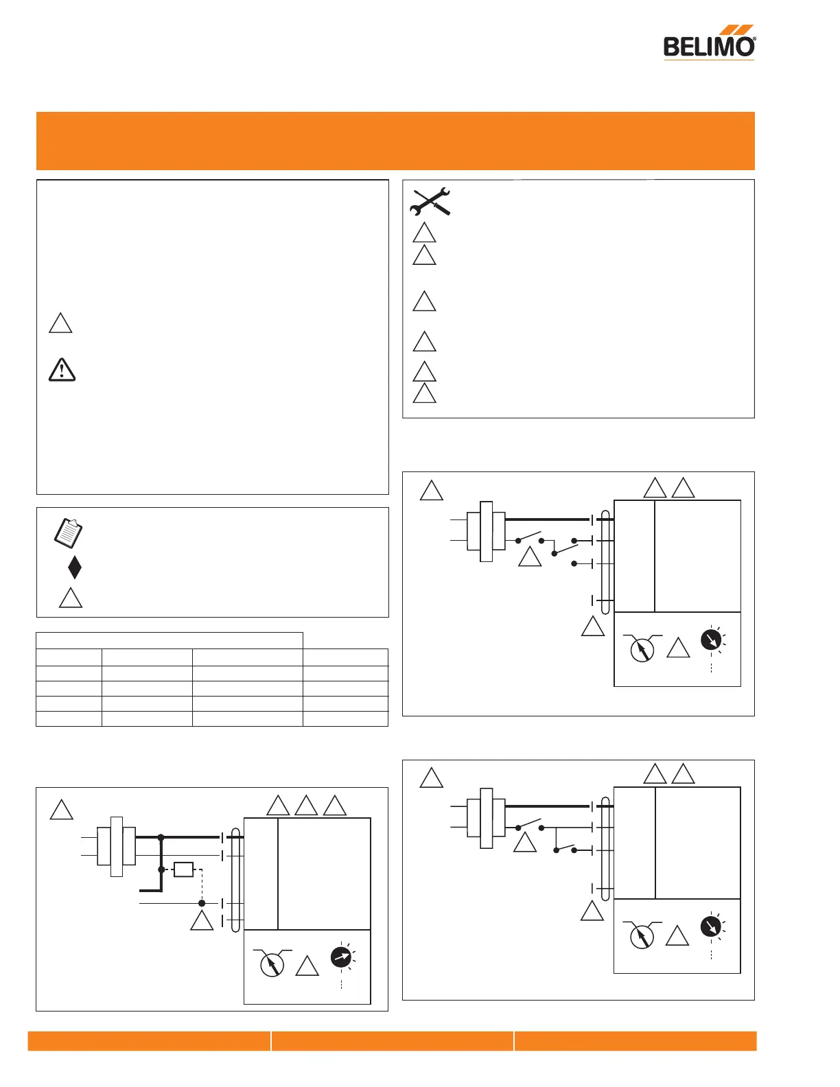
W179
2 to 10 VDC Control of LF24-SR-E US
Three-Position Control Signals
Switch A Wire 3-White (D) PositionWire 2-Red (x)
Open** Any Any
Closed (via spring)
Closed 24 VAC Open
Min-position*
Closed Open 24 VAC
Full Open*
Closed
* Desired position achieved by driving actuator with motor.
** An example would be to interlock the actuator power supply with the fan
motor starter.
24 VAC 24 VAC
Full Open*
24 VAC Transformer
Blk (1) Common
Red (2) + Hot
Wht (3) Y Input, 2 to 10V
Grn (5) U Output, 2 to 10V
Line
Volts
2 to 10 VDC
Control Signal
(–)
(+)
LF24-SR-E US
.8
.6
.4
.2
0
MIN
1
Default
CW CCW
Ω
3
2
7
21
21
26
31
32
5
3
21
24 VAC Transformer
Line
Volts
24 VAC
Blk (1) Common
Red (2) x + Min-position
Wht (3) D Y Full Open
Grn (5) U Output, 2 to 10V
LF24-SR-E US
.8
.6
.4
.2
0
MIN
1
Default
CW CCW
24 VAC Transformer
Blk (1) Common
Red (2) x + Min-position
Wht (3) D Y Full Open
Grn (5) U Output, 2 to 10V
Line
Volts
24 VAC
LF24-SR-E US
.8
.6
.4
.2
0
MIN
1
Default
CW CCW
Actuators: LF24-SR-E US
Meets cULus requirements without the need of an
electrical ground connection.
Provide overload protection and disconnect as required.
APPLICATION NOTES
21
26
W605_11
WARNING
Live Electrical Components!
During installation, testing, servicing and troubleshooting of this
product, it may be necessary to work with live electrical
components. Have a qualified licensed electrician or other
individual who has been properly trained in handling live electrical
components perform these tasks. Failure to follow all electrical
safety precautions when exposed to live electrical components
could result in death or serious injury.
 Loading...