800-543-9038 USA 866-805-7089 CANADA 203-791-8396 LATIN AMERICA / CARIBBEAN
21
N40067 - 7/11 - Subject to change. © Belimo Aircontrols (USA), Inc.
Actuators:
LMX LRX NMX AMX ARX ARX24-MFT-5
ARB24-MFT-5 GMX24-MFT GMX24-MFT-X1 GRX24-MFT-5 GRX24-MFT-7 GRB24-MFT-5
GRB24-MFT-7
Actuators with plenum rated cable do not have numbers on
wires; use color codes instead. Actuators with appliance
cables are numbered.
5
Meets cULus requirements without the need of an
electrical ground connection.
6
Equipment damage!
Actuators may be connected in parallel if not mechanically
mounted to the same shaft. Power consumption and input
impedance must be observed.
4
CAUTION
Indicates a potentially hazardous situation which, if not avoided,
may result in minor or moderate injury. It may also be used to
alert against unsafe practices.
Warnings and Cautions appear at appropriate sections throughout
this manual. Read these carefully.
Hazard Identification
INSTALLATION NOTES
APPLICATION NOTES
Only connect common neg (-) leg of control circuits.
11
For triac sink with common connection from the actuator
must be connected to the hot connection of the controller.
The actuator must be connected to the control board
common.
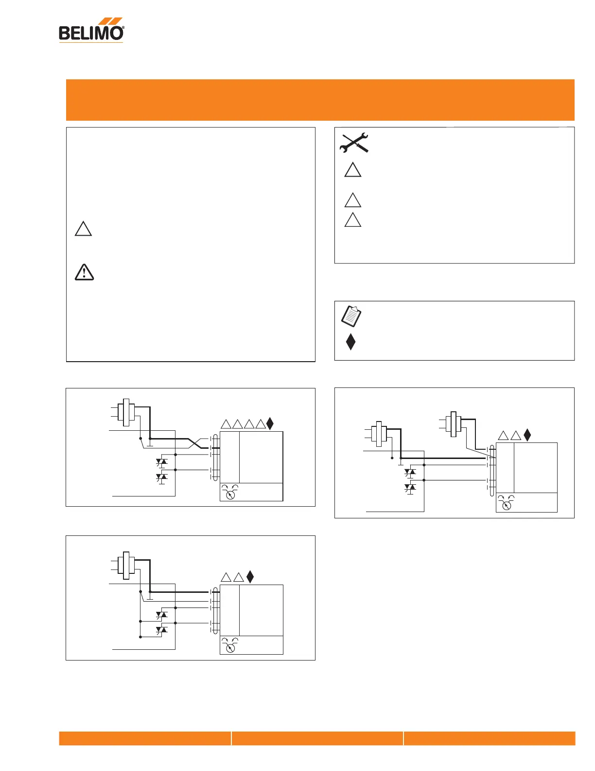
Triac Sink
Blk
(1)
Common
Red
(2)
+ Hot
Wht
(3)
Y
1
Input
Pnk
(4)
Y
2
Input
Org
(5)
U Output 2 to 10 V
ComHot
Controller
Line
Volts
4
11
24 VAC Transformer
5
6
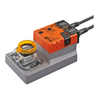
Triac Source
Blk
(1)
Common
Red
(2)
+ Hot
Wht
(3)
Y
1
Input
Pnk
(4)
Y
2
Input
Org
(5)
U Output 2 to 10 V
ComHot
Controller
Line
Volts
4
24 VAC Transformer
5
Triac Sink with Separate Transformer
Blk
(1)
Common
Red
(2)
+ Hot
Wht
(3)
Y
1
Input
Pnk
(4)
Y
2
Input
Org
(5)
U
Output 2 to 10 V
ComHot
Controller
Line
Volts
24 VAC Transformer
Line
Volts
24 VAC Transformer
4
5
W402_11
WARNING
Live Electrical Components!
During installation, testing, servicing and troubleshooting of this
product, it may be necessary to work with live electrical
components. Have a qualified licensed electrician or other
individual who has been properly trained in handling live electrical
components perform these tasks. Failure to follow all electrical
safety precautions when exposed to live electrical components
could result in death or serious injury.
Wiring for Damper Actuators and Control Valves
MFT, Non-Spring Return, 24V