800-543-9038 USA 866-805-7089 CANADA 203-791-8396 LATIN AMERICA / CARIBBEAN
9
N40067 - 7/11 - Subject to change. © Belimo Aircontrols (USA), Inc.
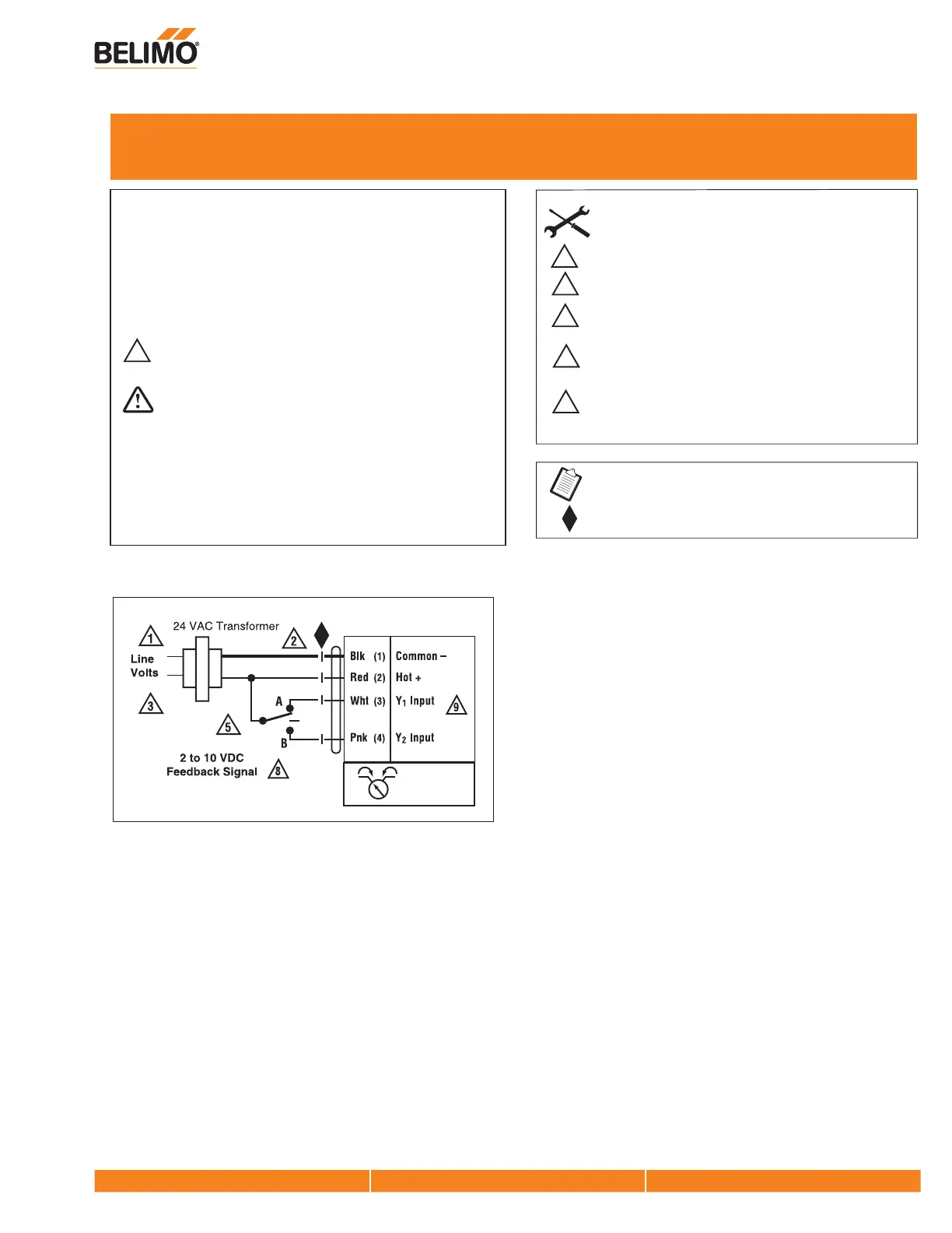
Wiring for Damper Actuators and Control Valves
Floating Point, Electronic Fail-Safe, 24V
Floating Point
Actuators: GKB24-3
Actuators may also be powered by 24 VDC.
1
Provide overload protection and disconnect as required.
3
5
8
Meets cULus requirements without the need of an
electrical ground connection.
Equipment damage!
Actuators may be connected in parallel. Power
consumption and input impedance must be observed.
2
CAUTION
Indicates a potentially hazardous situation which, if not avoided,
may result in minor or moderate injury. It may also be used to
alert against unsafe practices.
Warnings and Cautions appear at appropriate sections throughout
this manual. Read these carefully.
Hazard Identification
INSTALLATION NOTES
APPLICATION NOTES
W612_11
9
For triac sink the common connection from the actuator
must be connected to the hot connection of the controller.
Control signal may be pulsed from either the Hot (source)
or the Common (sink) 24 VAC line.
Contact closures A & B also can be triacs.
A & B should both be closed for triac source and open for
triac sink.
GKB24-3
WARNING
Live Electrical Components!
During installation, testing, servicing and troubleshooting of this
product, it may be necessary to work with live electrical
components. Have a qualified licensed electrician or other
individual who has been properly trained in handling live electrical
components perform these tasks. Failure to follow all electrical
safety precautions when exposed to live electrical components
could result in death or serious injury.