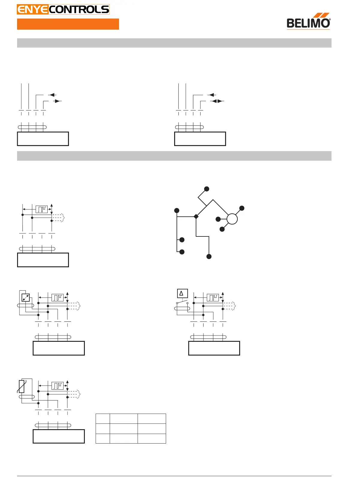
Wiring diagrams
AC/DC 24 V, modulating Operation on the MP-Bus
Y
U
1 32 5
–
+
DC (0)2…10 V
DC
2…10 V
Cable colours:
1 = black
2 = red
3 = white
5 = orange
1 32 5
–
+
Y
U
Sensor
MP
Cable colours:
1 = black
2 = red
3 = white
5 = orange
Functions
Functions when operated on MP-Bus
Connection on the MP-Bus MP-Bus Network topology
1235
MP
+
~
–
T
U
Y
A)
A) more actuators and sensors
(max.8)
There are no restrictions for the
network topology (star, ring, tree or
mixed forms are permitted).
Supply and communication in one
and the same 3-wire cable
• no shielding or twisting necessary
• no terminating resistors required
Connection of active sensors Connection of external switching contact
1235
MP
+
~
–
T
U
Y
A)
A) more actuators and sensors
(max.8)
• Supply AC/DC 24 V
• Output signal DC 0...10 V
(max. DC 0...32 V)
• Resolution 30 mV
1235
MP
+
~
–
T
U
Y
A)
p
A) more actuators and sensors
(max.8)
• Switching current 16 mA @ 24 V
• Start point of the operating range
must be parameterised on the MP
actuator as ≥ 0.5 V
Connection of passive sensors
1235
MP
+
~
–
T
U
Y
A)
Ni1000
PT1000
NTC
–28...+98°C
–35...+155°C
–10...+160°C
1)
850...1600 Ω
2)
850...1600 Ω
2)
200 Ω...60 kΩ
2)
A) more actuators and sensors
(max.8)
1) Depending on the type
2) Resolution 1 Ohm
NV24A-MP-TPC
Globe valve actuator, modulating, communicative, AC/
DC 24 V, 1000 N
Electrical installation
NV24A-MP-TPC • en-gb • 2020-01-22 • subject to changes
4
 Loading...