V3.3 07.2016•Subject to modifi cation
UL marked actuators is optional, please contact your local Sales Representative for details.
8
Functional data
Installation position Upright to horizontal (in relation to the stem)
Maintenance
Maintenance-free
Manual override Gear disengagement with push-button, can be
locked
Running time 90s
Safety Protection class IEC/EN
III Safety extra-low voltage
Degree of protection IEC/EN IP54
EMC CE according to 2004/108/EC
Mode of operation Type 1
Rated impulse voltage supply / control 0.8 kV
Control pollution degree 3
Ambient temperature -10...50°C
Non-operating temperature -20...80°C
Ambient humidity 95% r.h., non-condensing
Materials Housing EN-JL1040 (GG25 with protective paint)
Measuring pipe EN-GJS-500-7U (GGG50 with protective paint)
Ball Stainless steel AISI 316
Stem Stainless steel AISI 304
Stem seal EPDM Perox
• The device has been designed for use in stationary heating, ventilation and air conditioning
systems
and is not allowed to be used outside the specified field of application, especially
in aircraft or in any other airborne means of transport.
• Only authorised specialists may carry out installation. All applicable legal or institutional
installation regulations must be complied with during installation.
• The connection between the control valve and the measuring tube should not be separated.
• The device contains electrical and electronic components and is not allowed to be disposed of as
household refuse. All locally valid regulations and requirements must be observed.
Mode of operation
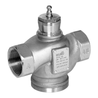
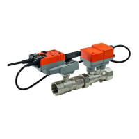
The actuator is comprised of three components: characterised control valve (CCV),
measuring pipe with volumetric flow sensor and the actuator itself. The adjusted maximum
flow (
max) is assigned to the maximum positioning signal (typically 10V).
The actuator control can be either communicative or analogue. The medium is detected
by the sensor in the measuring pipe and is applied as the flow value. The measured value
is balanced with the setpoint. The actuator corrects the deviation by changing the valve
position. The angle of rotation α varies according to the differential pressure through the
final controlling element (see volumetric flow curves).
Flow rate curves
Flow characteristic of the characterised
control valve
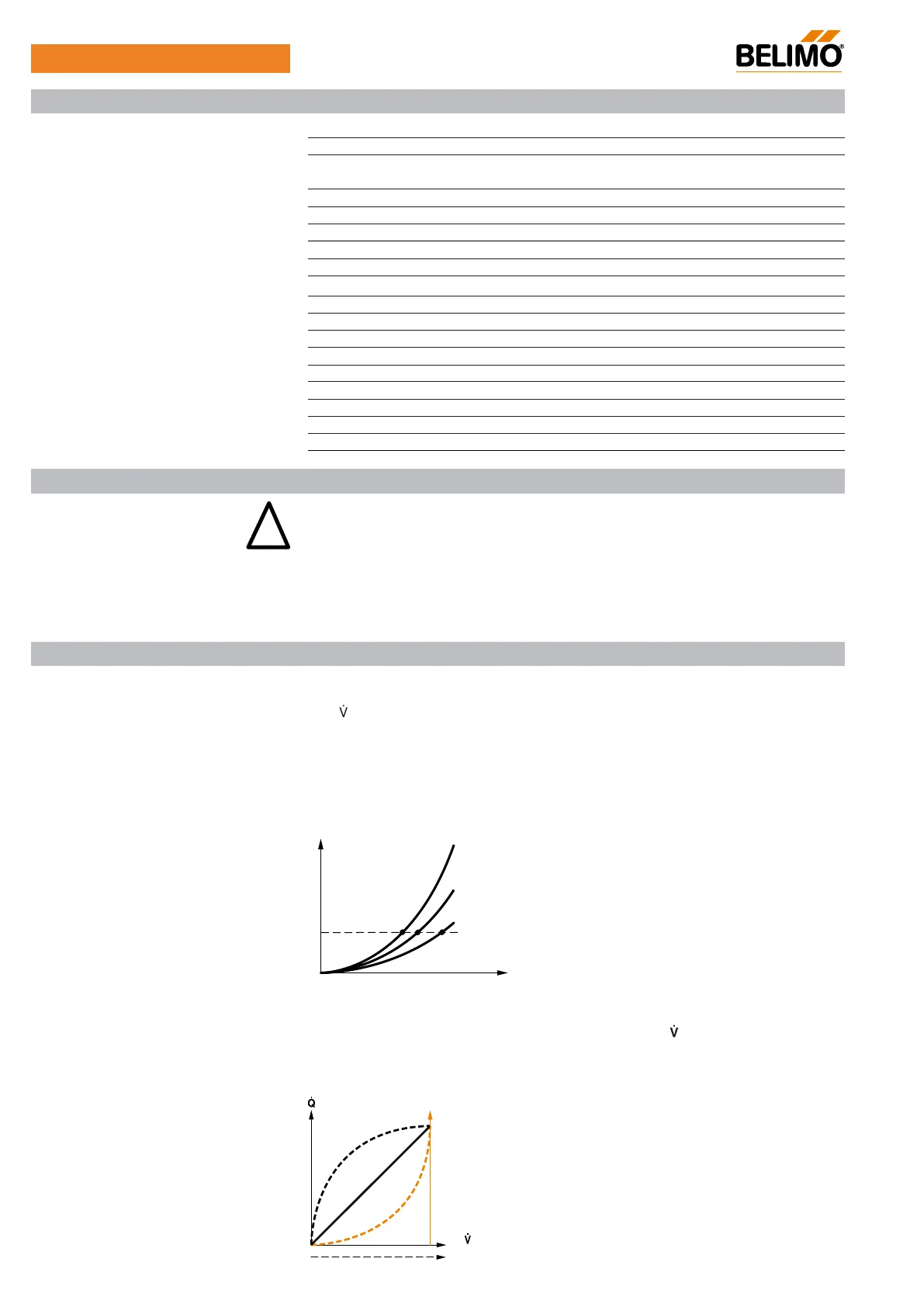
Heat exchanger transfer response
Depending on the construction, temperature spread, medium and hydraulic circuit, the
power Q is not proportional to the volumetric flow of the water
(curve 1). With the classical
type of temperature control, an attempt is made to maintain the control signal Y proportional
to the power Q (Curve 2) and is achieved by means of an equal-percentage valve
characteristic curve (Curve 3).
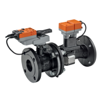
Characterised control valve (CCV) with sensor-operated flow
control, 2-way, with flange PN 16
Y
3
1
2
Safety notes
Product features
P6..W..E-MP
∆p
1
< ∆p
2
< ∆p
3
∆p
3
∆p
2
∆p
1
Technical data
 Loading...