ISS 3, SECTION C38.549
.............._,,__ . :::......... !_:_!
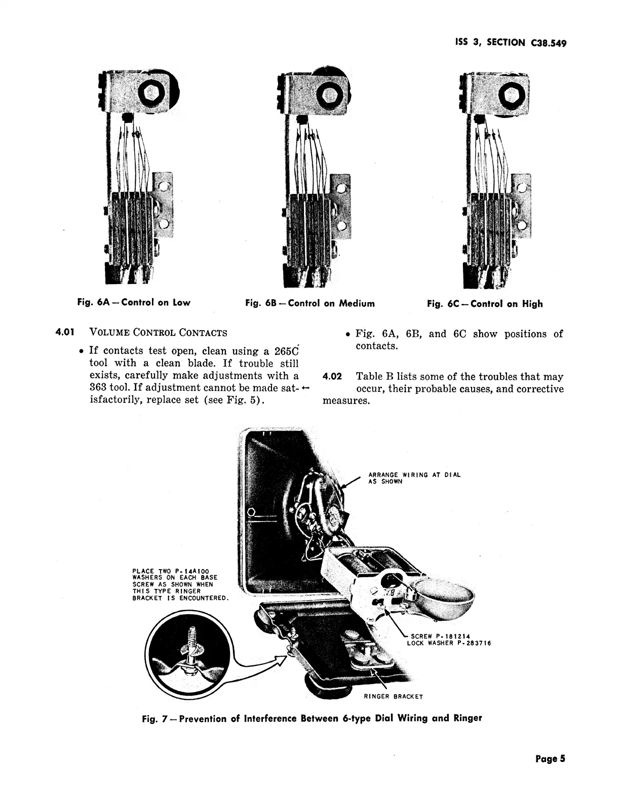
Fig. 6A -- Control on Low Fig. 6B -- Control on Medium Fig. 6C--Control on High
4.01 VOLUME CONTROL CONTACTS . Fig. 6A, 6B, and 6C show positions of
• If contacts test open, clean using a 265C" contacts.
tool with a clean blade. If trouble still
exists, carefully make adjustments with a 4.02 Table B lists some of the troubles that may
363 tool. If adjustment cannot be made sat- _ occur, their probable causes, and corrective
isfactorily, replace set (see Fig. 5). measures.
ARRANGE WIRING AT DIAL
AS SHOWN
PLACE TWO P-I4AIO0
WASHERS ON EACH BASE
SCREW AS SHOWNWHEN
THIS TYPE RINGER
BRACKET IS ENCOUNTERED. : _
SCREW P. 181214
LOCK WASHER P-283716
RINGER8RACKET
Fig. 7--Prevention of Interference Between 6-type Dial Wiring and Ringer
Page 5
 Loading...