Replacing the lightbulb
• Switch the appliance off and switch off the power supply at the wall.
Wait a few minutes to allow time for the halogen bulb to cool down.
• Place a towel on the floor of the oven cavity to protect the lamp cover
from damage if it falls.
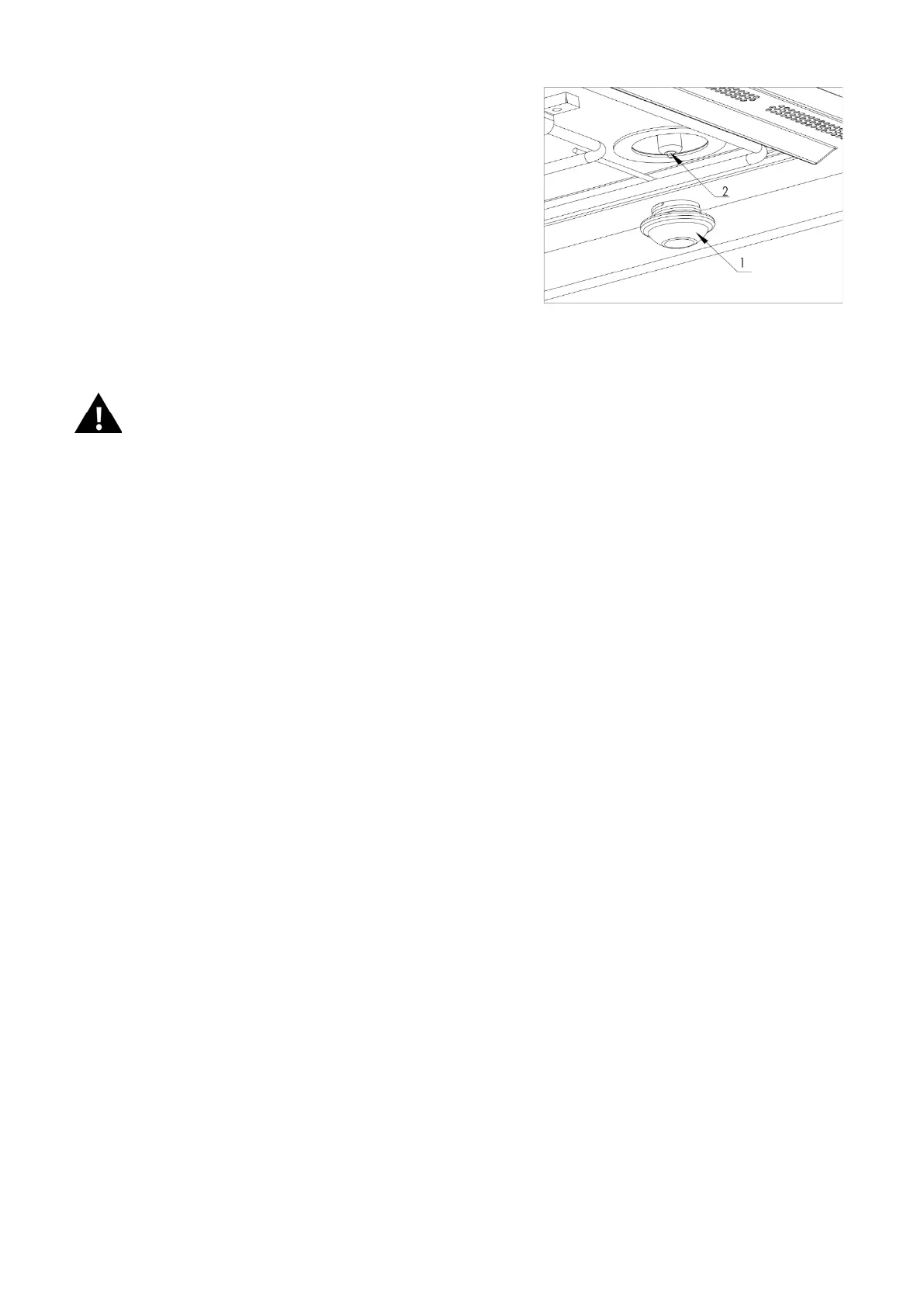
• Unscrew the lamp cover (1).
• This is a good opportunity to clean the lamp cover in warm soapy
water and dry it thoroughly.
• Remove the halogen bulb (2) WARNING the bulb may still be hot.
• Fit the new halogen lamp bulb, using one of the same type (220-240V
25W G9 halogen bulb).
• Replace the lamp cover.
• Connect the appliance back to the power supply.
If you are having difficulties replacing the lamp bulb, request an engineer service
visit.
INSTALLING THE APPLIANCE
Before The Installation
Open the oven door and remove the accessories and packaging material.
Please make sure that the oven is not damaged in any way checking that the oven door closes correctly and the inside of the
door and front oven panel are not damaged.
Do Not Use the Oven: If the power cable is damaged, if the oven does not function correctly or if it has been damaged or
dropped. Place the oven on a flat and stable surface prior to installation. The oven should not be installed close to any
heat source, radios or televisions.
During the installation, please make sure that the power cable does not come into contact with any moisture or objects with
sharp edges at the back of the oven. High temperatures can damage the cable. Warning: after the oven is installed you should
make sure the user can access the isolation switch.
Positioning the oven
This oven can only be used once it has been built into a housing unit, so that all electrical components are shielded. The
cabinetry must be able to withstand temperature rises. The cabinet unit must be well ventilated with an air intake of 500cm
2
minimum cross-section in the plinth at the base of the unit. The shelf supporting the oven must not go right back to the back
wall of the housing unit – there must be a gap of at least 100mm at the back to allow air to circulate. In a tall unit, any additional
shelves or drawers below the oven must also respect this 100mm gap.
Please note: Air vent is required in the plinth at foot of the base unit with a minimum cross section of 500cm
2.
There are 4
screw holes on the inner side of the oven door frame. Use the 4 wood screws to secure the oven into the housing unit.