EasyManua.ls Logo

Belmont Phot-X II 303 User Manual

Default Icon
35 pages
To Next Page IconTo Next Page
Page #1 background imageLoading...
Page #1 background image
·Floor Mount Type ..................FK1/FK2
·Mobile Type ...........................FM
·Room Mount Type..................RK
MODEL 303
DENTAL X-RAY
INSTALLATION
INSTRUCTIONS
This X-ray equipment may be dangerous to patients and operators
unless safe exposure factors and operating instructions are observed.
WARNING
R
0508(REV.0)

Other manuals for Belmont Phot-X II 303

Question and Answer IconNeed help?

Do you have a question about the Belmont Phot-X II 303 and is the answer not in the manual?

Belmont Phot-X II 303 Specifications

General IconGeneral
BrandBelmont
ModelPhot-X II 303
CategoryMedical Equipment
LanguageEnglish

Summary

SECTION 1 : TECHNICAL DATA

[2] OVERALL VIEW AND MAJOR COMPONENTS

1. FLOOR MOUNT TYPE (FK1/FK2)

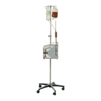
Overview of components for FK1/FK2 floor mount types.

2. MOBILE TYPE (FM)

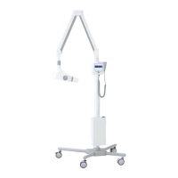
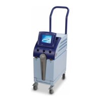
Overview of components for the mobile FM type.

3. ROOM MOUNT TYPE (RK)

4. SUB CONTROLLER

Identification of sub controller components.

[3] PHYSICAL DIMENSIONS

FM Mobile Type Dimensions

Physical dimensions for the PHOT-XII FM mobile type.

FK1/FK2 Floor Type Dimensions

Physical dimensions for the PHOT-XII FK1/FK2 floor types.

RK Room Type Dimensions

Physical dimensions for the PHOT-XII RK room type.

[3] TUBE HEAD THERMAL CHARACTERISTICS

Interval Between Exposures

Explains temperature rise and heat accumulation during exposures.

Duty Cycle Considerations

Specifies cool-down intervals between exposures to prevent overheating.

Cooling Curves and Rating Charts

Presents cooling curves and maximum rating charts for the tube head.

SECTION 2 : PRE-INSTALLATION INSTRUCTION

Support Requirements

Details structural support requirements for mounting the unit.

Electrical Requirements

Specifies power supply and wiring requirements for the system.

SECTION 3 : INSTALLATION INSTRUCTIONS

Installation Requirements

Lists tools and instruments needed for installation.

FK1/FK2 Type Installation

Instructions for mounting the FK1/FK2 type unit's plate and pole.

Horizontal Arm Installation (FK1/FK2)

Main Controller Fixing Plate Installation (FK1/FK2)

Balance Arm Installation (FK1/FK2)

Head Installation (FK1/FK2)

Main Controller Installation (FK1/FK2)

Sub Controller Installation (FK1/FK2)

Adjustment (FK1/FK2)

[3] INSTALLATION OF FM TYPE

Pole Assembly Installation (FM)

Steps for assembling the pole and attaching the base.

Arm Assembly Installation (FM)

Procedure for assembling the balance arm to the pole.

Controller Fixing Plates and Wiring (FM)

Balance Arm Swing Angle Adjustment (FM)

[4] INSTALLATION OF RK TYPE

Base and Column Installation (RK)

Steps for installing the base plate and column for the RK type.

Swing Arm Installation (RK)

Procedure for installing the swing arm assembly on the RK column.

Stool and Backrest Cushion Installation

Head Installation

Main Controller Installation

Sub Controller Installation

Adjustment

[5] HEAD ASSEMBLY INSTALLATION

[6] MAIN CONTROLLER INSTALLATION

FK1/FK2 & FM Type Controller Mounting

Mounting the main controller for FK1/FK2 and FM types.

RK Type Controller Mounting

Interconnecting Wire Connections

[7] SUB CONTROLLER INSTALLATION

Sub Controller Cable Connections

Connecting arm cable to power PC board and chassis grounding.

[8] HAND EXPOSURE SWITCH

Hand Exposure Switch Installation

Steps for installing and connecting the hand exposure switch.

SECTION 4 : POST INSTALLATION INSPECTION

FK1/FK2 Type Adjustments

Adjustments for FK1/FK2 type: level, swing friction, balance arm tension.

FM Type Adjustments

FM Type Adjustments

Adjustments for FM type: level, swing friction, balance arm tension.

RK Type Adjustments

RK Type Adjustments

Adjustments for RK type: level and swing arm friction.

[4] HEAD POSITIONING

SECTION 5 : CONTROL IDENTIFICATION AND OPERATION

Major Components and Control Identification

Identification of main and sub controller components and controls.

[2] FUNCTION OF CONTROLS

[3] OPERATING PROCEDURES

[4] HAND EXPOSURE SWITCH OPERATION

[5] ERROR CODES

[6] MAINTENANCE

SECTION 6 : POST INSTALLATION CONFIRMATION

Power Supply Voltage Confirmation

Verifying the power supply voltage is within the operable range.

Tube Potential Compensation Value Confirmation

Checking tube potential compensation values against labels.

Tube Current Confirmation

Procedure to confirm tube current self-diagnosis and adjustment.

Exposure Warning Light & Buzzer Confirmation

Exposure Warning Light & Buzzer Confirmation

Confirming activation of warning buzzer and illumination of warning light.

[5] CONFIRMATION OF LINE VOLTAGE REGULATION

SECTION 7 : INITIAL SETTING

Film Speed Setting

Configuring film speed settings for the x-ray unit.

Digital Imaging Speed Setting

[2] PRIORITY OF SELECTIONS

[3] ELECTRONIC CHIME ON/OFF

APPENDIX 1 : CIRCUIT DIAGRAM

Related product manuals