6
installation
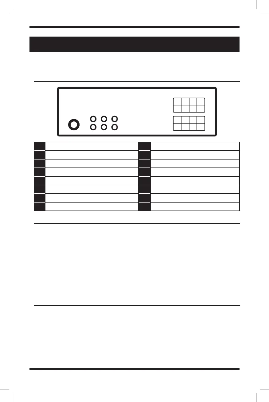
Please pay close attention to this diagram before installing this head unit.
• Run all ground leads to a common
ground point.
• Do not get the leads trapped under
a screw, or caught in moving parts
(e.g., seat railing).
• Before making connections, turn the
car ignition off to avoid short circuits.
• Choose the installation location
carefully so that the unit will
not interfere with normal driving
operations.
• Avoid installing the unit in areas
subject to dust, dirt, excessive
A Violet - Right rear speaker (+) 1 N/A
B Gray - Right front speaker (+) 2 N/A
C White - Left front speaker (+) 3 Blue - Antenna/Remote 12V (+)
D Green - Left rear speaker (+) 4 Red - Ignition Switch 12V (+) ACC
E Violet & Black - Right rear speaker (-) 5 N/A
F Gray & Black - Right front speaker (-) 6 Yellow - Battery Power 12V (+)
G White & Black - Left front speaker (-) 7 N/A
H Green & Black - Left rear speaker (-) 8 Black - Ground
wiring diagram
CAution
preCAutions
A
E
B
F
C
G
D
H
1
5
2
6
3
7
4
8
Antenna
RCA Outputs
(Sub/Front/Rear)
• Connect the yellow and red power
supply leads only after all other leads
have been connected.
• Be sure to insulate any loose
unconnected leads with electrical tape
for safety.
vibration, or high temperature, such as
in direct sunlight or near heater ducts.
• Use only the supplied mounting
hardware for a safe and secure
installation.