6 720 611 451 GB (03.11)
18
Installation
3.9.2 Installation of the flue
The standard 100 mm diameter horizontal flue system is
suitable for lengths up to 4 m.
Flues up to 650 mm do not require an extension duct
assembly.
Flues between 1600 mm and 4000 mm require exten-
sion duct assemblies.
NOTE: Flue lengths between 650 mm and 730 mm
cannot be accommodated. Refer to Fig. 17, 18, 19.
Standard 100mm system comprise:
• Flue turret
• Flue turret clamp
• Terminal assembly
• Wall sealing gasket and cover plate.
Refer to Fig. 20.
Instructions for fitting other flue systems are packed
with the relevant flue kit.
Check that the position chosen for the appliance is sat-
isfactory Refer to Fig. 16.
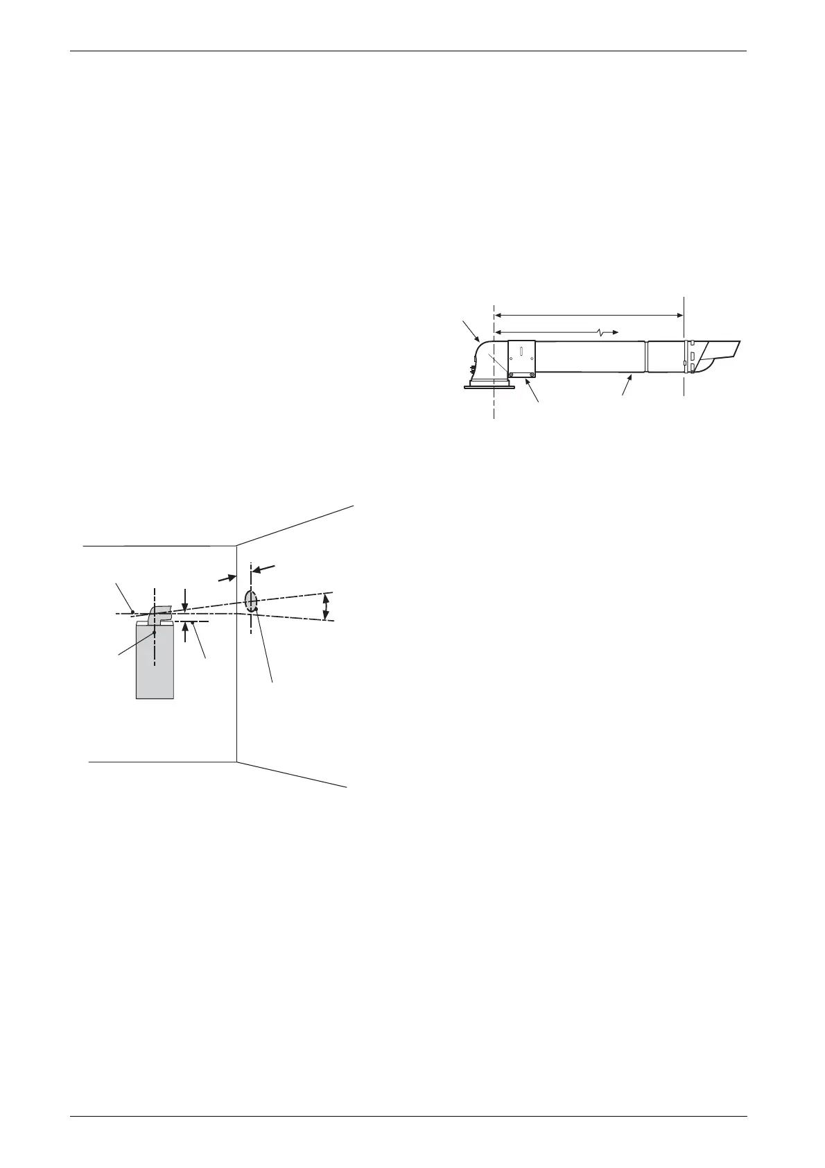
Fig. 16 Marking the position of a side flue opening.
Note: ensure there is adequate access to the
air/flue sampling points in the flue turret.
Fig. 17 Standard Flue
Centre line of
flue/air duct
Centre
line of
flue
opening
and
appliance Drilling
point for
flue duct
opening
H = 40mm for the Standard 100mm Horizontal Flue
H = 70mm for the Optional 125mm Horizontal Flue
3°
(30mm/metre)
Standard 100mm
horizontal flue 0.5°
(5mm/metre)
Top of wall
mounting
frame (not
boiler)
Appliance
H
120mm
6 720 610 602-08.3O
Maximum 650mm
Clamp
Flue
Turret
Terminal
Assembly
Outer
Wall
6 720 610 599 - 01.TD
Minimum 100mm