4
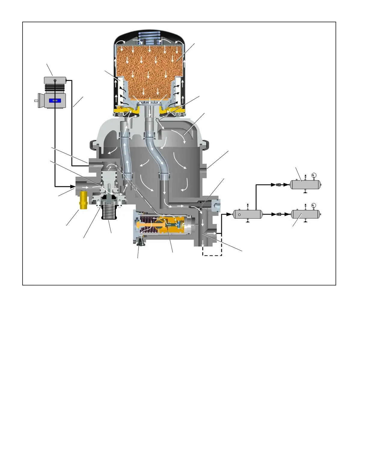
Figure 2 – Bendix
®
AD-9si
®
Air Dryer with a Governor — Charge Cycle
Compressor
Governor
Desiccant
Bed
Delivery
Check
Valve
Purge
Valve
Control
Port
Supply
Port
Front
Reservoir
Safety
Valve
Rear
Reservoir
Purge
Orice
Oil
Coalescing
Filter
Control
Line
Purge Air
Extended
Purge
Port
Exhaust
Exhaust
Delivery Port
CHARGE CYCLE (Refer to Figures 2 & 4)
When the compressor is running loaded (compressing air),
compressed air ows through the compressor discharge
line to the inlet (IN 1) port of the air dryer body. The
compressed air often includes contaminates such as oil,
oil vapor, water, and water vapor.
Traveling through the discharge line and into the air dryer,
the temperature of the compressed air falls, causing
some of the contaminants to condense and drop to the
bottom of the air dryer and purge valve assembly. These
contaminants are ready to be expelled at the next purge
cycle. The air then ows through the inlet tube and into
the desiccant cartridge, where it ows through an oil
separator – or coalescing lter if equipped with a Bendix
®
PuraGuard
®
oil coalescing cartridge – which removes water
in liquid form, as well as liquid oil and solid contaminants.
Air then ows into the desiccant drying bed and becomes
progressively more dry as water vapor adheres to the
desiccant material in a process known as adsorption.
Dry air exits the desiccant cartridge, through the outlet tube,
then ows to the delivery check valve. Some air exiting
the desiccant cartridge is diverted through the orice into
the purge volume area. The delivery check valve opens,
supplying air to the two delivery ports. The purge reservoir
lls, storing air that will be used to regenerate the desiccant
during the purge cycle.
The air dryer will remain in the charge cycle until the air
brake system pressure builds to the governor cut-out
setting of approximately 130 psi.
Turbo
Cut-Off
Valve
(open)