18
SECTION 9
(TESTING PROCEDURES)
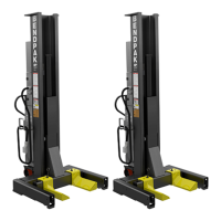
Single Column Test
(Repeat these procedures on each Column in Single
Mode.)
Lifting Test
1. After setting the Operation Mode to SINGLE on the
control panel, raise the lift unloaded by pressing and
holding the “UP” button to check if the carriage rises
normally.
If the Carriage raises slowly or jerks, the Cylinder may
have to be bled to release any trapped air in the hydraulic
system. If not, go to Step 3.
2. Raise the carriage above about 5”\127mm and
loosen the Cylinder Bleed Screw on the top of the
Cylinder one full turn or until air or oil ows out. DO NOT
completely remove bleed screws. Retighten after trapped
air has escaped. (See Fig 9.1)
Safety and Lowering Test
3. With the Carriage above 21”/533mm press and hold
the “PARK” button that became available when the lift
passed the indicated height. The lift will lower onto the
nearest safety lock. Continue holding the “PARK” button
and then check that the Carriage is securely on the safety
lock before continuing.
NOTE: When the PCL-18B is not loaded with a vehicle
the SPEED should be set to Rabbit mode or a fault
condition may be detected.
4. Press and hold the “DOWN” button. The carriage will
start to move up to clear the safeties and then down to the
to the ground or until the “DOWN” button is released.
Emergency Button Test
5. Test the Emergency Stop Button by hitting the
Emergency Stop Button while the lift is rising or lowering.
The lift should immediately stop. To Reset, twist button
clockwise. The button will pop back out.
Multiple Column Test
Repeat the Lift Test, Safety Test, Lowering Test, and
Emergency Stop Button Test procedure for each of the
other Columns in the other Operation Modes: Pair and
Team.
Remember:
-Pair mode will control the Column directly across
from the Column control panel being operated.
-Team mode will control the entire system.
POST-INSTALLATION CHECK-OFF
√ Columns properly lowered and stable.
√ Wheel and Arm Pins properly attached.
√ Electric power supply confirmed.
√ Safety Locks functioning properly.
√ Check for hydraulic leaks.
√ Oil level.
√ Lubrication of critical components.
√ Check for overhead obstructions.
√ All Screws, Bolts, and Pins securely fastened.
√ Surrounding area clean.
√ Operation, Maintenance and Safety Manuals
on site.
√ Perform an Operational Test with a typical
vehicle.
DO NOT completely remove
Bleed Screw. One full turn
should purge trapped air.
Cylinder Bleed
Screw
Fig. 9.1