17
SECTION 8
(INITIAL START-UP AND PLC SYSTEM OVERVIEW)
1. Make sure the power unit reservoirs are full with four
(4) gallons of 10-WT hydraulic oil or Dexron-III automatic
transmission uid each.
2. Apply light axle grease to the inside of the posts where
the slide blocks glide.
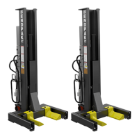
3. Once electrical power is connected to Column A and
the communication cables routed to the other Columns,
turn the Main Power Switch to the “ON” position. (See
Fig. 8.1)
If any of the Column heights are higher than the other one
press the “DOWN” button. If the heights still do not match
correctly see Maintenance section for calibration
instructions.
5. Pressing MODE allows the operator to control he
movement of the entire system in Team mode (See Fig
8.2), Columns A and B in Pair mode or Column A by itself
in Single Mode
6. Pressing SPEED allows the operator to change the
speed at which the lift will lower when the DOWN button is
pressed. Rabbit mode (See Fig. 8.3) allows for a quicker
descent while Turtle mode (See Fig 8.4) allows for a
slower, more precise descent.
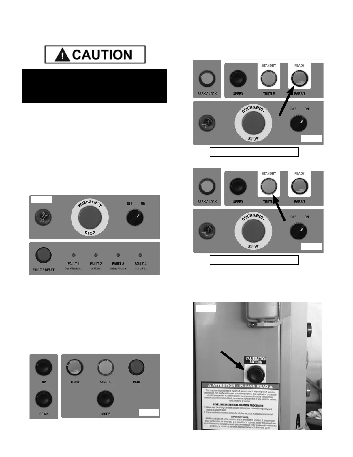
7. Pressing CALIBRATE SYSTEM (Column A Control
Panel only) will set the current height of the lift carriages
as the 0 point or ground level. (See Fig 8.5)
ENSURE ALL OF THE COLUMNS ARE IN THE
LOWERED POSITION AND NOT RESTING ON A
RAISED HYDRAULIC JACKING DOLLY.
Fig. 8.1
Fig. 8.2
Rabbit Mode
Turtle Mode
Fig. 8.3
Fig. 8.4
Fig. 8.5