Do you have a question about the Benetech GT5105A and is the answer not in the manual?
Highlights the instrument's functions including backlight, data holding, and measurement modes.
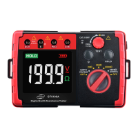
Details the components and indicators displayed on the instrument's LCD screen.
Guidance on checking battery voltage and connecting test leads correctly.
General safety warnings and symbol implications for safe instrument operation.
Important notes and warnings regarding potential hazards during measurements.
Detailed steps for performing accurate earth resistance measurements with standard test leads.
Instructions for conducting ground voltage measurements.
Steps for performing earth resistance tests using different gears.
How to use the data hold, save, review, and clear functions.
Procedure for simple earth resistance measurement using a 2-wire method.
Instructions for battery replacement, case cleaning, and general upkeep.
Guidance on contacting support for instrument issues and repair procedures.
The BENETECH GT5105A is a Digital Earth Resistance Tester designed for measuring grounding resistance of various power facilities wiring, electrical equipment, lightning protection equipment, and other grounding devices. It can also measure ground voltage. The instrument is controlled by an intelligent microcontroller chip, ensuring high accuracy and reliability. However, it is not suitable for harsh outdoor environmental conditions such as rain or lightning.
| Brand | Benetech |
|---|---|
| Model | GT5105A |
| Category | Test Equipment |
| Language | English |