10
Introduction
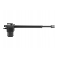
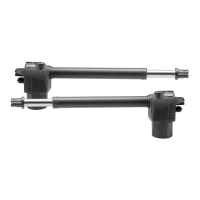
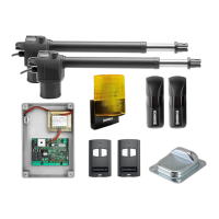
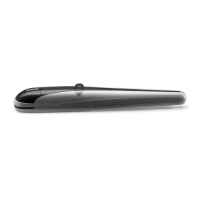
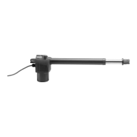
Electromechanical operator to activate swing gates,
available in the following models:
BILL30M: with motor powered at 230 VAC.
BILL30MA: with motor powered at 115 VAC.
For every model, the RGHT (DX) version is also available to
install the system on the right gate leaf, and the LFT (SX)
version is available for installation on the left gate leaf.
In case of doubt, as shown in the instruction manual, the
wording DX (right) or SX (left), which identifies the different
models, can be seen by opening the release handle.
For simplicity reasons, this manual shows the SX motor
for left gate leaves. For the DX (right) versions, installation
dimensions and instructions are the same.
The main dimensions are shown in Fig. 1.
• Before installing the system, read the instruction herein.
• It is mandatory not to use the BILL 30 item for applications
different from those indicated in the instructions herein.
• Supply the end user with instructions for using this
system.
•
The end user should receive special instruction manual.
• All Benincà items are covered by an insurance policy for
damages and injuries caused by manufacture faults. It is
however required that the machine bear the CE marking
and original Benincà parts be used.
General information
To ensure a good operation of these automatic devices,
the gate to be automated should meet the following
requirements:
- good strength and stiffness.
- hinges should have a minimum backlash and allow for
smooth and regular manual operations.
- when closed, the gate leaves should correctly overlap
for their entire height.
Warning: BILL30 is not equipped with electric limit switches
or mechanical stoppers. It is mandatory that the gate leaf
be equipped with mechanical stoppers fitted to the ground
(Fig.2 ref. A and B).
Operating limits
The following tables show the permitted maximum weight
and width figures of the gate leaves.
Max gate leaf weight (kg)
100 300 350
Max gate leaf width (m)
2,5 2,1 1,8
In case of wind effect the limits can be significantly reduced.
How to install the system
1) Define the height of the system from ground (the most
centred possible with respect to the main door and
corresponding to a rugged crossbeam).
2) Weld the P plate, taking account of figures X and Y of
Fig. 2/3.
3) Release the actuator, as shown in the instruction manual.
When the gate is closing, temporarily lock the S* bracket by
keeping the K measure as per Fig. 2/3. In these conditions,
the actuator must not be positioned entirely at end of stroke,
but 10mm extra-stroke should be still available.
By manually opening the gate leaf, check that the actuator
does not hit the leaf or the pillar.
4) Only after this check, carry out the final welding of the S
bracket. The actuator should be perfectly flat.
Important: the respect of dimensions indicated in Fig. 3
ensures the optimal operation of the automatic system.
These different dimensions may cause malfunctions.
In any case, the manufacturer shall be held unharmed
with respect to damages caused by the non-respect of
the dimensions indicated.
If it is not possible to carry out welding, adjustable brackets,
which can be mounted by using screws (art B.SR), are
available as optional accessory.
Fix the actuator to the bracket by means of screws and nuts
supplied. Use washers as shown in Fig. 4.
Note: The difference between measures X and Y shall
be never exceed 40mm. Greater differences cause the
unsmooth movement of the gate.
Dimensions M and X should be carefully checked to avert
that the actuator hits the pillar (dim. M) or the leaf (dim. Z).
The total stroke of the actuator is around 320mm. The stroke,
however, cannot be entirely used. An extra stroke of around
10 mm should be always provided both in the closing and
opening phases.
* In the BILL 30 geared motor, the difference in height of
brackets P and S shall be nil. These brackets should be
therefore fitted at the same height (Fig. 1, ref. A}
Wire connections
BILL 30 is supplied with a pre-cabled wire, around 80 cm
long, to be connected to the junction box fitted to the pillar:
BLACK Gear 1
BROWN Gear 2
GREY Motor, common
Yellow/Green Earth
Note:
The motor cable shall be replaced only by an authorised
assistance centre.
IT IS MANDATORY to connect the system to ground by using
the special GND terminal, as provided by regulations in force.
WARNING
The insurance policy, which covers any damages or injuries
caused by manufacture faults, requires that the installation
comply with regulations in force and Benincà original
accessories be used.
TECHNICAL DATA
BILL 30M BILL 30MA
Motor power supply
230Vac
50/60Hz
115 Vac
50/60Hz
Absorbed rating 240W 240W
Consumption 1,1 A 2,2 A
Max. thrust 2800 N 2800 N
Operating jogging 30 % 30 %
Protection level IP54
Operating temperature -20°C / +50°C
Capacitor 8 μF 31,5 μF
Useful stroke 300 mm
Noise <70 dB
Lubrication Permanent grease
Weight 5,7 kg 5,7 kg
 Loading...