9
8) ELECTRIC CONNECTIONS
The cables necessary for the installation of BOB can vary according to the accessories installed.
No connection cable is supplied.
Fig. 7 indicates the cables for standard installation.
List of cables
Connection Type
A Mains power supply to the control unit 3x1,5mm
2
B Motor connection 4x1,5mm
2
(3x0,5mm
2
BOB30ME)
C Photocell transmitter connection 2x1,0mm
2
D Photocell receiver connection 4x1,0mm
2
E Key selector connection for external command 2x1,0mm
2
F Flashing signal light connection 2x1,5mm
2
G Connection of the aerial built-in the flashing light RG 58
Legenda
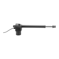
1 Motoreducer
2 Photo-electric cells
3 Key selector (external) or digital keyboard
4 Flash-light
5 Electronic board
The cables used must be suitable for the type of connection. For example, for connection protected by raceways use
H03VV-F cables, for cables in the outdoor environment always use the H07RN-F type.
TECHNICAL DATA
BOB21M
BOB30M/BOB30ME
Power supply 230Vac 50/60Hz
Absorbed current 1,5 A 1,8 A
Thrust 1800 N 2300 N
Jogging
30%
IP44
Protection degree
Operating temperature -20°C / +50°C
Capacitor 9 μF 12,5 μF
Useful stroke:
- with 2 stoppers
- without stoppers
270 mm
325 mm
Noise level <70 dB
Lubrification Permanent grease
Weight 8,2 kg 8,6 kg