5
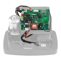
1) CONTROL PANEL CORE
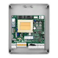
1.1) WIRE DIAGRAM
Wire connections shown in Fig. 1 are described hereunder:
Terminals Function Description
L-N-GND
Power
supply
Input, 230VAC 50Hz (CORE)
Input, 115VAC 50/60Hz (CORE 115V))
(1-Phase/2-Neutral/GND-Ground connection)
MOT-COM-MOT Motor Connection to motor: (MOT-move/COM-Common/MOT-move)
N-BLINK LAMP
Output, connection to Flashing light
CORE: 230 Vac 40W max.
CORE 115V: 115 Vac 40W max.
SWO SWO Input, OPENING limit switch (Normally Closed contact)
SWC SWC Input, CLOSING limit switch (Normally Closed contact)
PHOT (CLOSE) PHOT
Input, connection to safety devices, Normally Closed (N.C.) contact (e.g. photocells): configurable through DIP3).
In “Service man” mode, it activates the CLOSE function.
In this case connect a Normally Open (N.O.) key.
STOP STOP
Input, STOP key (N.C. contact)
Can assume the Close or Pedestrian function (contact N.O.) see “Advanced Programming” paragraph.
COM COM Common, all control inputs.
P.P. (OPEN)
Step
by-Step
Input, step-by-step key (N.O. contact). Can assume the OPEN function see paragraph “Advanced Programming”.
In “Service man” mode, it activates the OPEN control function.
24 VAC 24Vac Output, 24Vac/200mA max accessory power supply.
SCA SCA
Contact free from voltage, not insulated for the connection of open gate indicator lamp. Open contact with
closed door leaf. Flashing light during the door leaf movement. With open door leaf, the contact is closed.
ENC1 ENCODER Input, connection of the encoder (OPTIONAL). See section 5
SHIELD-ANT Antenna Connection of the antenna to the incorporated radio-receiver module (SHIELD-screen/ANT-signal).
Note: The control unit uses a “P2” key with the same functions of the Step-by-Step push-button. This is useful to control the automatic
system during installation (only with DIP2: OFF).
2) CHECKING CONNECTIONS
1) Cut off power supply.
2) Manually release the door, move it at around half stroke and lock it again.
3) Reset power supply.
4) Send the step-by-step (P.P.) control signal through the P2 key, P.P. or remote control.
5) The door leaves should open. If not, with stopped motor, it is sufficient to invert the move wires of the motor (MOT/MOT) of the
motor and the limit switches (SWO/SWC).
6) Proceed with regulations described in “STROKE ACQUISITION & SLOWDOWNS”
3) TRIMMER FUNCTIONS
3.1) TW - If the Encoder device is installed, it assumes the function of regulating anti-crushing sensitivity. When turned in a clockwise
direction, sensitivity is increased.
In the absence of an Encoder device, regulate the maximum duration of opening and closing manoeuvres. It must be preset approx. 4s
more with respect to the actual stroke time of the system. The adjustment ranges from 3s to 180s maximum. If the stroke acquisition
and slowdowns procedure is executed, the position of the trimmer has no effect on the operation time.