5
CP.J3-SW CONTROL UNIT
ELECTRICAL CONNECTIONS
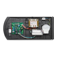
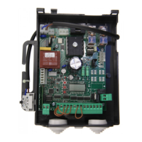
The follows table shows the electrical connections in Fig. 1:
Terminals Function Description
L/N/GND Power supply 230Vac 50 / 60Hz input (L-Phase / N-Neutral / GND)
MOT/+ENC- Motor/Encoder Quick connector for the connection of motors provided with Encoder
ANT/SHIELD Antenna
Built-in radio receiver antenna connection
ANT: Signal / SHIELD: Display
COM General Common for all control inputs.
S.S. Step-by-Step
Step-by-step key input (N.O. contact). The control unit executes a command at each
S.S. impulse according to the sequence: OPEN>STOP>CLOSE>STOP>OPEN...
STOP STOP STOP button input (N.C. contact)
PHOT Photocell Photocell input active only in the closing phase (N.C. contact).
BLINK Flashing 24Vdc flashing connection 15W max.
+ 24V - 24 Vac/dc Power supply output accessories 24Vdc/500mA max.
J6 X.BE Quick connector for KNX interface card (item X.BE - See paragraph KNX)
M5 LED Quick connector for optional additional LED light connection (item__)
M6 Battery charger Quick connector for optional battery charger card connection (item_)
QUICK PROGRAMMING
The procedure described below enables to programme one or more transmitters and perform control panel AUTOSET.
PLEASE NOTE: Preliminary conditions for quick programming:
- Receiver with less than 64 stored transmitters
- Autoset never performed.
If mistakes are made during the quick programming phase, disconnect the mains power supply and restart the initial procedure.
Quick Programming Steps
1 Remove mains supply if present, then restore mains voltage.
2 The “Service Light” of the control unit starts to flash.
3 Press the hidden key of the transmitter to be stored, the “Service Light” stays on.
4 Press the desired key to associate with the receiver within 5s, the “Service Light” flashes a few times to confirm receipt, then
flashes again.
5 Repeat steps 3 and 4 for the following transmitters to be stored, up to a maximum of 64 transmitters.
6 To move to the next autoset phase, press and hold down the key of a transmitter already stored until the AUTOSET phase
starts
8 The LD1/2/3 LEDs light up cyclically and a number of movements are performed automatically, calculating optimal operating
parameters. If the autoset operation is successful, the panel stops in the open position and the LED lights remain steady for 5s
to confirm AUTOSET correctly carried out.
The maximum time for programming the first transmitter is 60 seconds.
If necessary proceed with manual configuration of Trimmers and DIP-SWITCHES according to the type of installation.
To skip the quick programming phase and proceed with manual programming, press the PU1 PU2 keys for 1s at any time.
ARC TRANSMITTERS
IMPORTANT, PLEASE READ CAREFULLY:
The radio receiver in this product is compatible only with ARC (Advanced Rolling Code) transmitters which, thanks to 128 bit coding,
guarantee superior anti-copying security.

 Loading...