21
1) TECHNICAL DATA
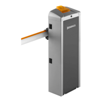
LADY5
Feed 230 Vac
Motor feed 24 Vdc
Motor consumption 1,6 A
Torque 205 Nm
Degree of protection IP44
Jogging Intensive use
Operation temp. -20°C/+50°C
Opening time min. 3,6"
Lubrication Permanent grease
Noise level <70dB (A)
Weight 50 kg
2) POSITIONING THE SPRING AND THE ACCESSORIES FOR USE
Depending on the length of the bar and on the type of accessories installed, before putting the spring under tension it is necessary to choose the correct
point in which to attach the spring to the lever.
The correct fastening point (“A”, “B” or “C” - Fig.1), must be chosen in table 1, depending on the length of the bar and on the type of accessories you
intend to install.
TAB. 1
LADY5/LADY5.I
Bar lenght (m)
Accessories for use
2,2 2,7 3,2 3,7 4,2 4,7 5,2
NA
C C B B B A
LADY.P(1)
C C C B B A A
LADY.P(2)
C C C B B A A
VE.RAST
C C B B A A
LADY.P(1) + VE.RAST
C C B A A
LADY.P(1) + VE.AM
C C C B A A A
LADY.P(2) + VE.AM
C C B B A A
LADY.P(1) + VE.RAST + VE.AM
C B B A A
SC.RES
C C B B A A
LADY.P (1) + SC.RES
C C B A A
SC.RES + VE.AM
C B B A A
LADY.P(1)+ SC.RES + VE.AM
C B B A A
VE.RAST + VE.AM
C B B A A
Key
NA
No accessories
LADY.P(1)
Protection profile (only upper).
LADY.P(2)
Protection profiles (upper and lower).
VE.RAST
Aluminium skirt.
VE.AM
Mobile support for bar.
SC.RES
Sensitive resistive edge (complying EN12878).
Attention:
The installation of the
VE.RAST
interferes with the use of the
SC.RES
and vice versa.
The installation of the
LADY.L
lights kit does not influence the balancing of the bar
3) LAYING THE FOUNDATION PLATE (FIG.3)
After having arranged the passage of the cables (power supply, accessories, etc.), put the foundation plate in position, referring to the measurements in fig.3.
4) FIXING THE BAR (FIG.4)
The bar is fixed to the plate using the support and the screws provided, as illustrated in Fig.4. We recommend installing any accessories for the bar
(protective profiles, lights, edge, skirt, etc.) before fixing it to the plate.
5) PREPARING THE BARRIER FOR RIGHT OR LEFT (FIG.5)
If the opening direction reversion is required, proceed as follows. If it is not necessary, go to the next section:
• Entirely unload the spring by loosening it and unhooking it from the “L” anchoring lever
• with reference to Fig. 5, invert the position of the “F1” and “F2” mechanical stoppers. Before loosening the stoppers, back-off the related locking
grains (see section HOW TO ADJUST THE MECHANICAL STOPERS)
• unlock the geared motor (see “Manual Operation”) insofar as to render the L hooking lever idle.
• according to the length of the road barrier arm and accessories used, choose the correct hooking position, as indicated in paragraph “Positioning of
the spring and accessories”.
• hook the spring in the new position. Fig. 5 shows the differences between a right-hand road barrier and a left-hand one.
 Loading...