EasyManua.ls Logo

Beninca PONY - Control Unit CP.PONY Connections; Programming the CP.PONY Control Unit - Introduction

Beninca PONY
80 pages
Go to English
To Next Page IconTo Next Page
To Previous Page IconTo Previous Page
Loading...
2
0
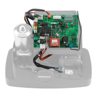
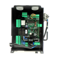
Control unit CP.PONY connections
Except
f
or the mains connection cable, all electric connections have a volta
g
e o
f
24V
and can also be per
f
ormed by unquali
f
ied sta
ff
.
C
onnect all accessories makin
g
reference to the layout in fi
g
ure 33 and to the “Electric
connections” paragraph,
f
or that concerning the types o
f
cable.
T
o ma
k
e connect
i
on eas
i
er, t
h
e accessory c
l
amps
h
ave co
l
ours t
h
at correspon
d
to
those of the control unit.
F
i
g
.
1
KEY
:
1
Line protection
f
use
2
Accessories
p
rotection
f
use
3
“P
G
M” programming button
4
P
rogramm
i
ng
b
utton
5
LCD
A
B
DE
SC
RIPTI
O
N
O
F THE TERMINAL B
O
ARD
S
C
LAMP
CO
L
OU
R
D
E
SC
RIPTI
O
N
PH
O
T
G
REEN
N
C input from the RX photocell. The two clamps are connected to each other by a wire
(
ref. “A
)
.
R
emove this wire onl
y
if the
p
hotocell is connected
.
STOP
B
LACK
S
T
O
P input N
C
contact for auxiliary
S
T
O
P” command
(
optional
)
. The two clamps are connected to each other by a wire
(
ref. “A
)
. Remove
t
his wire only i
f
a device is connected to this input.
PP
WHITE
S
te
p
-b
y
Ste
p
command in
p
ut from the ke
y
selector. At ever
y
im
p
ulse sent from the selector a se
q
uence of commands, which can be co
n
-
g
ured usin
g
the PP function, is performed cyclically.
24V YELLOW
2
4Vdc output for photocells power supply. Respect the polarities + and - in the connections
(
ref “B
)
.
BLINK
R
ED
2
4Vdcashin
g
li
g
ht connection output
SHIELD/ANT
B
LUE
C
onnection of the aerial built-in theashin
g
li
g
ht.
W
hen connecting the R
G
58 cable, the external shield must be connected to the
S
HIELD clamp.
1
2
3
4
5
PHOT
STOP
PP
RXTX
24V
-
+
BLINK
SHHIELD
ANT
P
ro
g
rammin
g
of the control unit allows the re
g
ulation of all parameters indispensable
f
or the correct
f
unctionin
g
o
f
the automatio
n
.
P
ro
g
rammin
g
takes place by means o
f
a series o
f
menus that can be selected
f
rom
the L
C
D. A function corres
p
onds to ever
y
menu, which will be described successivel
y
.
PG
M
The “P
G
M” button allows to enter programming, select the pre
-
selected menu and con
f
irm the value selected.
Th
e
b
utton a
ll
ows to scro
ll
t
h
e var
i
ous
i
tems
i
n t
h
e menu an
d
the values to be set c
y
clicall
y.
P
G
M
+
B
y press
i
ng
and “P
G
M” at the same time, return to the upper
level of the menu or, if already at the first level, exit pro
g
rammin
g.
Programming the CP.PONY control unit - Introduction
LCD
PGM
W
ith the dis
p
la
y
o
ff
, the
button
p
erforms a Ste
p
-b
y
-Ste
p
command.
T
his
f
unction can be use
f
ul durin
g
the pro
g
rammin
g
and inspection phases.
P
ressin
g
the PGM button causes the immediate stop of any leaf movement
.

Related product manuals