Do you have a question about the Beninca THINK-I and is the answer not in the manual?
Declaration based on EC directives for EMC and Low Voltage.
Product conforms to EMC, LVD, and Radio Equipment directives.
Install onnipolar switch with contact distance >= 3mm.
Ensure differential interrupter and overcurrent protection.
Ground shutter to conductive mass as per regulations.
Separate or insulate leads with different voltages (min 1mm insulation).
Secure leads with an additional fixture near terminals.
Interrupt power before accessing electrical parts for installation/maintenance.
Verify all connections before powering on the unit.
Bridge unused N.C. inputs for proper operation.
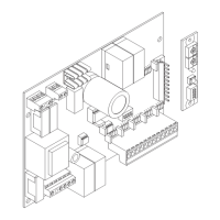
Details for 230Vac single-phase and 400Vac three-phase motor connections.
Connection for 230Vac flashing light and negative electric brake.
WARNING: Output, 230Vac 0,5A max.
Output for pickup auxiliary capacitor connection.
Free N.O. contact for timed courtesy light.
Output for accessory power supply 24Vac/0.5A max.
Output for indicator light or checked devices (PhotoTest).
Common terminal for limit switches and photocells.
Input for OPEN limit switch (N.C. contact).
Input for CLOSE limit switch (N.C. contact).
Inputs for photocells, can be disabled in opening/closing phases.
Input for STOP push-button (N.C. contact).
Input for OPEN push-button (N.O. contact).
Input for CLOSE push-button (N.O. contact).
Input for pedestrian push-button (N.O. contact).
Input for step-by-step operation (N.O. contact).
Common terminal for all other control inputs.
Input for safety edge contact, resistive or mechanical.
Connection of the antenna to the receiver board.
Output for the 2nd radio channel of the receiver.
Emergency stop connection; requires N.C. switch.
Jumper settings for 400Vac or 230Vac mains power supply.
Input for 230Vac/50Hz single-phase mains power.
Input for 400Vac/50Hz three-phase mains power.
Step-by-step guide to access and modify control unit functions.
Allows presetting digit values for functions.
Allows activation/deactivation of functions like dip-switches.
Sets automatic closure delay time.
Adjusts motor operation time for opening/closing phases.
Sets gate leaf stroke time for partial opening.
Adjusts sensor sensitivity for opening/closing phases.
Sets activation time for courtesy light.
Adjusts motor protection switch triggering current.
Enables or disables automatic gate closure.
Enables or disables the multi-flat function.
Enables or disables rapid closure after photocell activation.
Selects operation mode for step-by-step button and transmitter.
Enables or disables flashing light before motor start.
Selects OPEN input mode for normal or timed operation.
Enables or disables Service Man operation mode.
Enables or disables lock function with delayed stop.
Configures photocell activation in opening/closing phases.
Selects output mode for SCA/TESTPHOT.
Enables or disables single failure check.
Enables or disables the anti-crash amperometric sensor.
Enables or disables phase check for three-phase power supply.
Activates or deactivates movement reversion for sensor/DAS triggers.
Enables or disables the motor protection switch.
Enables/disables rapid reversion after closing phase photocell.
Displays the number of completed open/close cycles.
Resets the control unit to its default values.
Instructions for short-circuiting unused photocell inputs.
Shows input status on the display based on activation.
Details common error messages and their troubleshooting.
Identifies fuses for accessories, logic board, flashing light, and transformer.
Details on power supply, output, and maximum motor power.
Specifications for accessory power supply and protection level.
Information on operating temperature and radio receiver.
Instructions for releasing side tabs and removing cover masks.
Procedure for slackening hinge screws to allow cover opening.
| Brand | Beninca |
|---|---|
| Model | THINK-I |
| Category | Control Unit |
| Language | English |