15
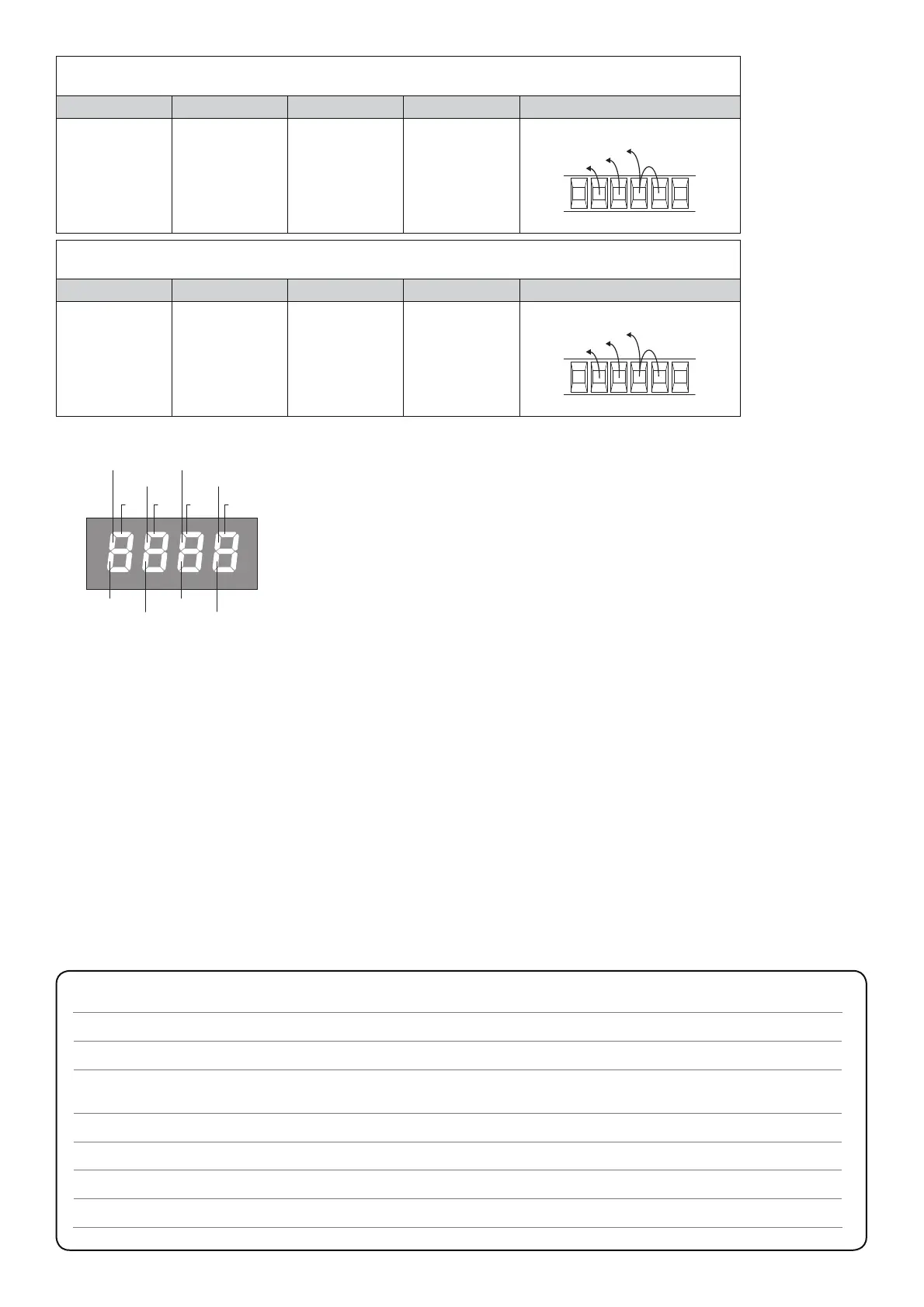
2 pairs of photocells, active in both opening and closing (PHOT1 e PHOT2)
+ 1 pair of photocells, active in the closing phase only (PHOT3):
Logic PHO 1 Logic PHO 2 Logic PHO 3 Logic PHO 4 JUMPERS
OFF OFF ON ON
18 2019 21
RX1
RX2
RX3
2 pairs of photocells, active only in the closing phase (PHOT1 e PHOT2)
+ 1 pair of photocells, active in both opening and closing phases (PHOT3):
Logic PHO 1 Logic PHO 2 Logic PHO 3 Logic PHO 4 JUMPERS
ON ON OFF OFF
18 2019 21
PHOT4
PHOT2
DAS
P.P. PED OPEN CLOSE
Each input is matched to one segment of the display; in the event of activation, it switches
on according to the following diagram.
The Normally Closed (N.C.) inputs are represented by vertical segments. The Normally
Open (N.O.) inputs are represented by horizontal segments.
Error messages
The control unit checks the correct operation of the safety devices.
In the event of faults the following messages can be displayed:
ERR1 Error, check photocells. Check connections and the correct operation of photocells.
ERR2 Activation of the anti-crash amperometric sensor. Check the presence of any obstacles.
ERR3 Check of single failure has negative result. Contact the technical assistance.
ERR4 Triggering of the motor protection switch. Check the value of the parameter SAFM and check the motor consumption.
ERR5 Lack of one of the three phases. Check the correct connection of power supply of the three-phase mains.
Fuses
F1 Protection fuse, accessories
F2 Protection fuse, logic board
F3 Protection fuse, flashing light and electric brake.s
F4 Primary protection fuse of the transformer.
TECHNICAL DATA
Power supply
230 Vac 50/60 Hz
Output supply
1 motor 230Vac single-phase / 400Vac three-phase
Power maximum motor
230Vac single-phase: 800 W
400Vac three-phase: 2200 W
Output supply accessories
24Vdc 500mA max.
Protection level
IP54
Operating temp.
-20°C / +50°C
Radio receiver
Removable connector for radio receiver

 Loading...