14
8) EXAMPLE INSTALLATION
The cables necessary for the installation of TOM can vary according to the accessories installed.
No connection cable is supplied.
Fig. 11 indicates the cables for standard installation.
List of cables
Connection Type
A Mains power supply to the control unit 3x1,5mm
2
B Motor connection
TOM 30M/40M/ 50M: 4x1,5mm
2
+ 2x0,5mm
2
(SWO/SWC)
TOM 30E: 4x1,5mm
2
+ 3x0,5mm
2
(ENCODER)
TOM 30ME/40ME/ 50ME: 3x1,5mm
2
+ 3x0,5mm
2
(ENCO-
DER)
C Photocell transmitter connection 2x1,0mm
2
D Photocell receiver connection 4x1,0mm
2
E Key selector connection for external command 2x1,0mm
2
F Flashing signal light connection 2x1,5mm
2
G Connection of the aerial built-in the flashing light RG 58
Legenda
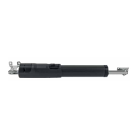
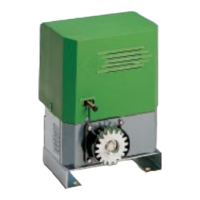
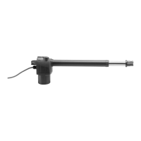
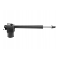
1 Motoreducer
2 Photo-electric cells
3 Key selector (external) or digital keyboard
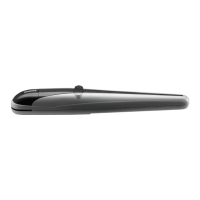
4 Flash-light
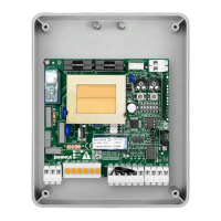
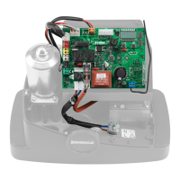
5 Electronic board
The cables used must be suitable for the type of connection. For example, for connection protected by raceways use
H03VV-F cables, for cables in the outdoor environment always use the H07RN-F type.
9) MANUAL AND EMERGENCY MANOEUVRE (FIG.12)
In the event of a power cut or breakdown, proceed as follows to operate the wings manually (refer to figures A*,B*,C,D,E):
• Rotate the protective door (fig. A*)
• After inserting the customized key C, turn it anti-clockwise (fig. B*)
• Open the protective flap of the release mechanism (Fig. C) and pull out the supplied release key (Fig. D).
• Insert the special release key supplied (fig. E) and turn it 90°, as shown in fig. F.
• It is now possible to open/close the wing manually.
• To restore automatic operation, return the release key to its initial position.
• Remove the release lever and close the protective door.
TECHNICAL DATA TOM.30M TOM.40M TOM.50M TOM.30ME TOM.40ME TOM.50ME TOM.3024E TOM.4024E TOM.5024E
Power supply 230Vac 50/60Hz 24 Vdc
Absorbed current 1 A 0.7 A
Thrust 2000 N 1500 N
Jogging 30% Intensive
Protection degree IP44
Operating temperature -20°C / +50°C
Capacitor 9 μF -
Useful stroke 300mm 400mm 500mm 300mm 400mm 500mm 300mm 400mm 500mm
Noise level <70 dB
Lubrification Permanent grease
Opening time 90° 18s 24s 30s 18s 24s 30s 11s (24V) 15s (24V) 19s (24V)
Mechanical stops Open/Close
Encoder no si
Limit switch si no