DSP 2500 Inverter System
10.15.07 6 028-0009-200
5. Terminals and Operating Elements
All operating elements are located on the front, installer connections are found on
the rear the inverter.
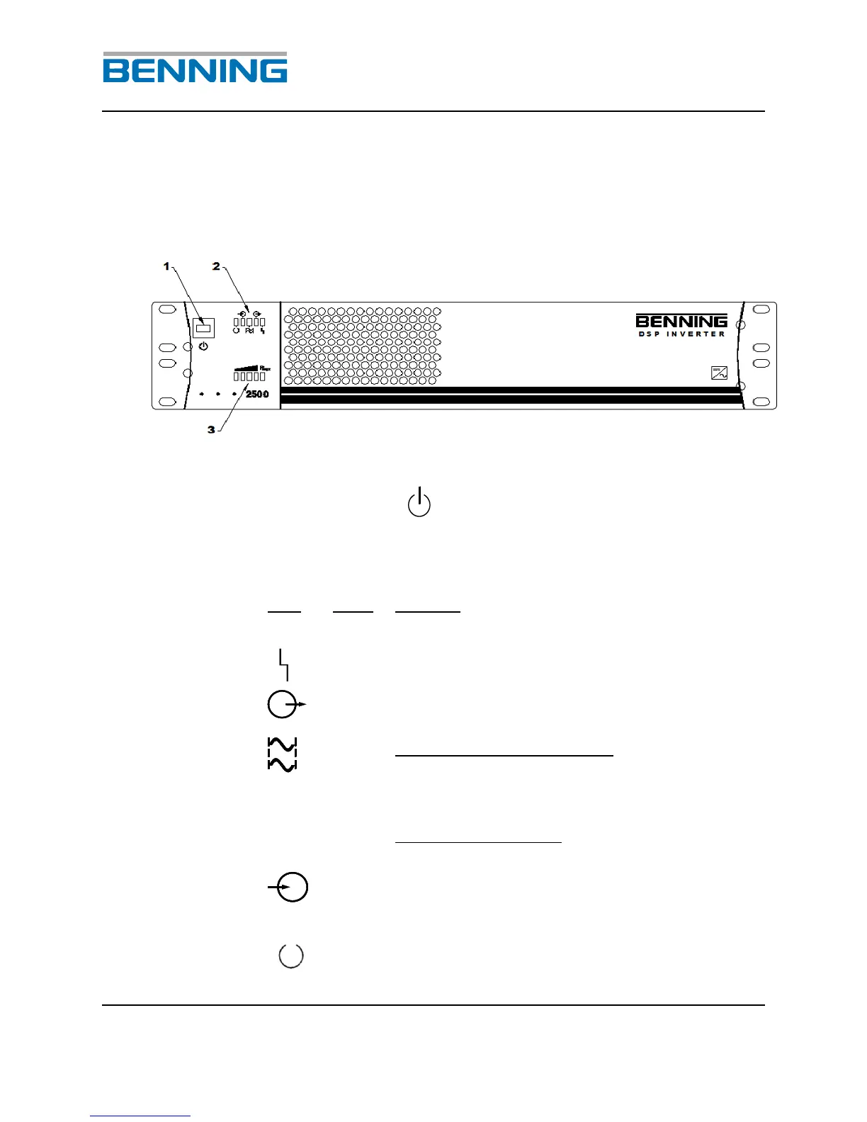
Fig. 2: Front view of the DSP Inverter
1 Unit switch ON/OFF
2 LED’s for indicating the inverter status
Output voltage present and connected
through to the load receptacles
LED in continuous operation:
The output voltage of the inverter is phase
locked to the other inverters in the system;
parallel operation only
LED in flashing mode:
MASTER functionality; parallel operation only
The DC input voltage is within the acceptable
input range. If light is blinking the DC voltage
is out of range.