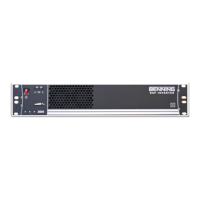
DSP 2500 Inverter System
10.15.07 22 028-0009-200
11. Commissioning the Inverter
Attention!
Commissioning may be carried out only by properly
instructed trained personnel!
1) Switch on the DC supply by closing/inserting the disconnecting
device
The LED is lit
(this indicates the DC input voltage present and is within the
acceptable input range)
2) Switch on the inverter by pressing the ON/OFF switch.
Immediately after switching on the inverter, the LED is lit
(this indicates the inverter is switched on)
When the start-up phase of the inverter has been completed, the
following LED will also illuminate: (indicates that output
voltage of the inverter is present)
3) Switch on the loads
The greater the connected load, the more LED’s will be lit to
indicate the approximate inverter output power.
12. Maintenance / Repair
This inverter was designed for continuous operation and is practically
maintenance free. To ensure correct functioning, it is recommended that the
flow of cooling air be checked periodically and dust be removed from the
cooling fan area as necessary. Verify bolt torque value as indicated in Section
9 of this manual.