DSP 2500 Inverter System
10.15.07 8 028-0009-200
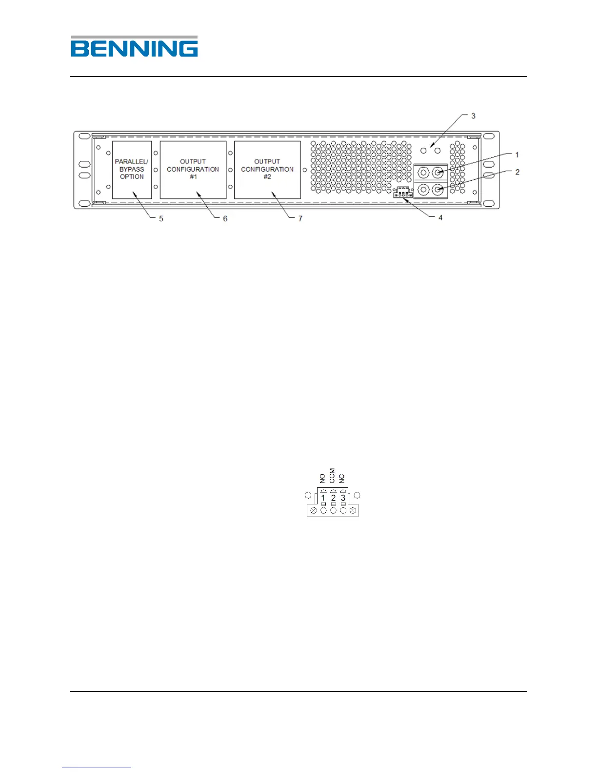
Fig. 3: Rear view of the DSP inverter
1 (+); Copper bar / threaded stud; plus (+) connection for the DC
input of the inverter. Arranged for ¼” x 5/8”, two-hole crimp lug
2 (-); Copper bar / threaded stud; negative (-) connection for the
DC input of the inverter. Arranged for ¼” x 5/8”, two-hole crimp
lug.
3 Grounding location (PE).
4 Potential free central fault signal.
5 Parallel Bypass Option Panel. (See section 14 for options)
6 Output Configuration #1 Panel. (See section 14 for options)
7 Output Configuration #2 Panel. (See section 14 for options)