Q7T4-FP71G LCD Monitor Service Guide
Circuit Operation Theory
3
Confidential
support detect mode and DPMS control.
3.) MTV312M64: To stored the source code which is accessed by MCU to run program.
4.) EEPROM: We use 24C04 to store all the adjustable data and user settings.And use 24C02 to
store DVI EDID data.
A-2.) Control board introduction:
There are 6 keys for user's control which includes “Power”, “Enter”, “Up/Plus”,
“Down/Minus” , “Exit”, and “iKey” . The following descriptions are the introduction of these keys.
(1) Power key: to turn/off power of monitor
(2) “Enter” key: to enter sub-menus or select items.
(3) “Up/Plus key: to select previous and to increase adjustment
(4) “Down/Minus” key: to select next and to decrease adjustment
(5) “Exit” key: to back to previous menu, or leave OSD (auto save)
(6) “iKey”: to perform auto adjustment
(7) LED:
It indicates the DPMS status of this LCD monitor; green light means DPMS on (Normal
operating condition). Amber light means DPMS off (Powersaving).
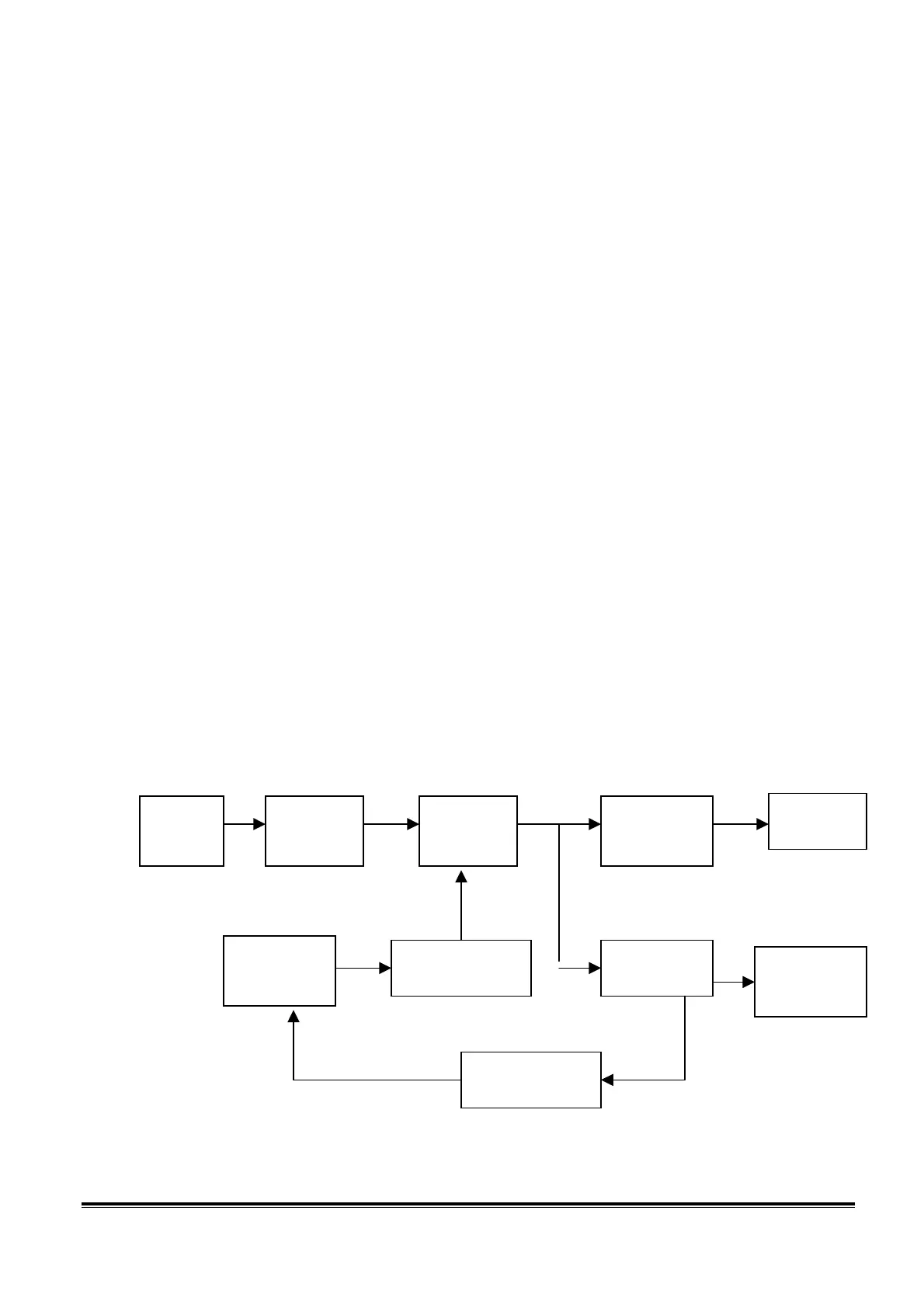
A-3.) Power board diagram:
Fig.1
EMI Filter Rectifier and
filter
Isolation power
transformer
Rectifier and filter
PWM controller
Switching element
Feedback Isolation
Inverter circuit
Rectifier and filter
LDO regulator
 Loading...