manual. Any such parts will undergo
inspection to verify the claim. Replacement
parts supplied prior to this may be charged,
and a credit supplied upon subsequent
validation of the warranty claim.
Consumable items are specifically not
included within the scope of the warranty.
Note (iii)
Notification is required immediately a fault is
suspected.
The manufacturer will not accept
responsibility for any additional damage that
has been caused, expense incurred, or
consequential loss resulting from any failure
of the heater(s).
SPECIAL RISK AREAS
Where it is proposed to install a heater
within a special risk area (e.g. an area
containing flammable vapours where petrol
engined vehicles are stored parked or
serviced where paint spraying occurs, or
where woodworking machinery or other
flammable dust creating process’s are
employed then restrictions, additional
regulations concerning the heater flue wiring
or controls may apply.
It is strongly recommended that you contact
Benson Technical before installation
Caution
When used in room sealed mode it may be
possible to install Variante heaters in areas
containing flammable vapours, high levels of
airborne dust combustible dust chlorinated or
halogenated hydrocarbons degreasing
solvents styrenes other laminating materials
or airborne silicones. Benson Technical
should be contacted before installation .
Failure to do so may invalidate or reduce
guarantee cover.
2.0 Installation
The location chosen for the heater must
allow for the fitting of an effective flue
system.
The location must also allow for adequate
clearance for the air supply, return air
circulation, gas supply, electrical supply,
whilst also providing good and safe working
access.
The heater must be installed so that it is
level, supports for the heater must be
sufficiently robust to withstand the weight of
the heater and any ancillary equipment
Any combustible material adjacent to the
heater or flue system must be so placed or
shielded so that its surface temperature does
not exceed 65
0
C. Generally a free blowing
heater should be located at a height
(measured from floor level to the base of
unit) as detailed within section 2.1
VRABD free blowing heaters are at their
most effective when located as close to the
working area as possible. However care
should be exercised to avoid directing the
discharged air directly onto the occupants of
the area to be heated.
Where the passage of cold air causes
problems (e.g. by entrances, loading bays
etc) it is considered favourable if the heater
is positioned so as the discharge towards or
across the cold air source from a distance
from 1.5m - 6m dependent upon the size of
the entrance and the air throw characteristics
of the heater. On exposed walls heaters
should be positioned so as to discharge
towards, or along the length of the exposed
wall.
In areas where it is proposed that more than
one heater is to be installed, a general
scheme of circulation should be drawn up
and maintained, thereby offering the best
heat distribution. Air pressure within the area
heated and the outside air pressure must
remain the same, factors influencing this
would be the presence of extraction systems,
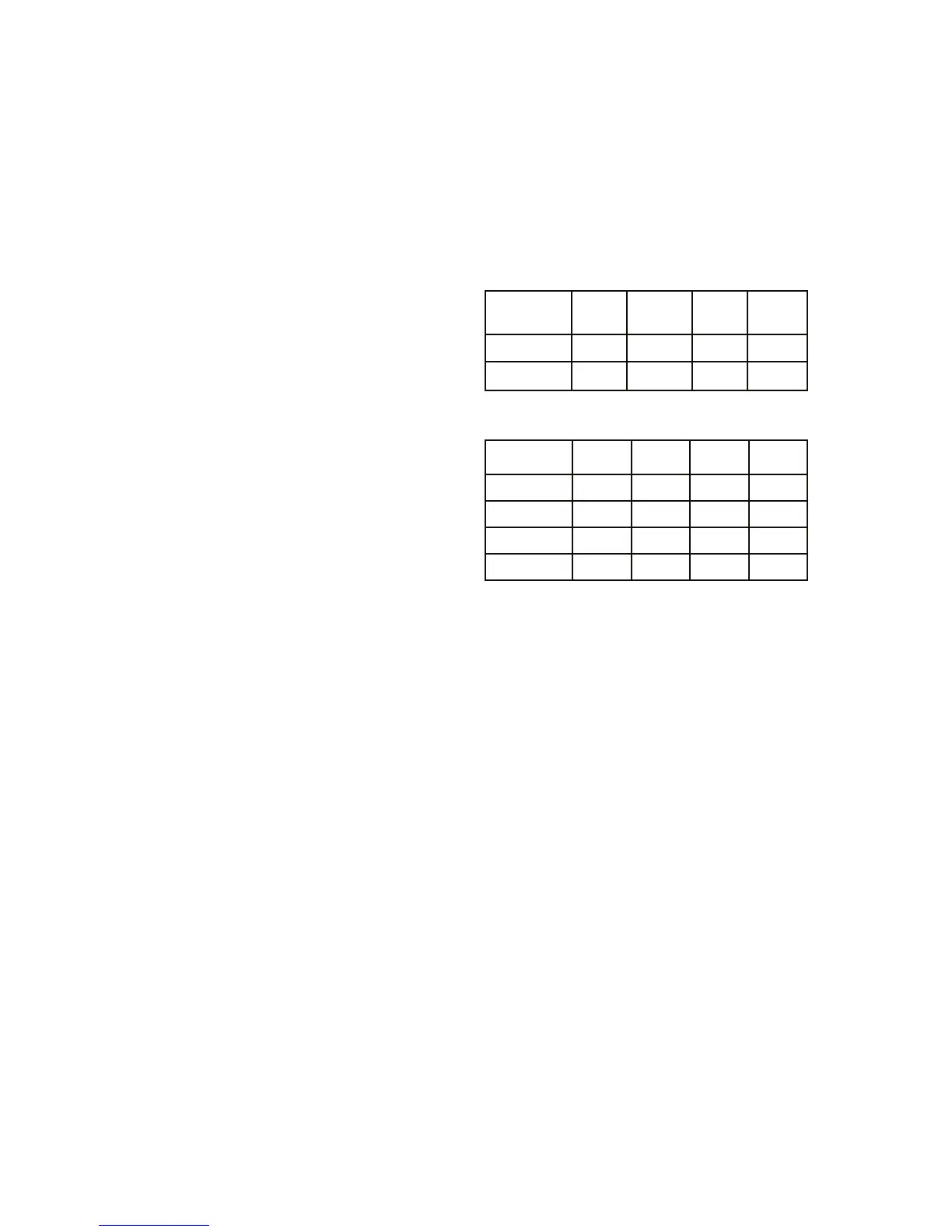
Model
VRA/C
250 330 410 490
Min 2.4 2.4 2.4 2.4
Max 5.0 5.0 5.0 5.0
Model 250 330 410 490
Above
300 300 300 300
Below
300 300 300 300
Right side
250 250 250 250
Left side
950 950 950 950
Clearances VRABD in mm
Left hand side = burner compartment side