4
Status mode selection MOdE: rotate to change the thermostat mode
between AUTO, PARTY, and OFF, press to save. The press from
status mode automatically escapes from menu.
Economy temperature selection ECOt: Rotate to select the desired
economy temperature and press to enter. This temperature is used
when programming time is OFF in AUTO status mode.
Heating and cooling mode selection I- - S: Rotate to select the ther¬-
mostat mode between I (heating) and S (cooling), press to save.
The selected mode is identied on the display with the presence of
the radiator icon in AUTO mode (radiator icon ON means heating
mode, radiator icon OFF means cooling mode). In cooling mode the
request versus the chiller appliance remain ON till the room temper-
ature moves below the target.
Time of the day: rotate to change the hours, press to save. Move to
minutes; rotate to change minutes, press to save.
Day of the week: rotate to change the day, press to save
Programmed times day 1-7: rotate clockwise to set hour ON, rotate
anticlockwise to select hour OFF. Clockwise and anticlockwise rota-
tion move ahead the time. Press to save. Rotate clockwise to move
to the following day. It is possible to program together days 1…5 and
days 6-7 with the same pattern in a single operation.
PL: rotate to select the password value, press to enter inside the
technical menu. Rotate to select the parameters:
1 = COUP - ENCODING between the receiver and the transmitter
2 = CH - RADIO FREQUENCY modication
3 = frost protection temperature selection
4 = hysteresis ON value selection
5 = hysteresis OFF value selection
6 = SENS – TEMPERATURE SENSOR ON-OFF. The temperature
sensor can be activated or deactivated
7 = calibration of the temperature sensor
Exit: escape from main menu.
INSTALLATION AND OPERATING INSTRUCTIONS
Unlike the conventional thermostat, this control separates the func-
tion in two units. The receiver serves for wiring connections and
heat on/off control. The transmitter serves as the user interface and
for temperature sensing/control. The two units are linked by radio
frequency (RF). The RF communication is two directions from the
transmitter to the receiver; therefore if transmitter-receiver are not
coupled, alarm of missing communication is visible on the transmit-
ter display.
THE TRANSMITTER is a wall-mounted thermostat. The transmitter
can be located wherever a conventional room ther-
mostat would normally be sited. No wiring is re-
quired, as the transmitter is battery powered.
THE RECEIVER is connected to the boiler, and can
replace a conventional mechanical or electronic time
clock. The receiver arrives pre-cabled and ready to
be xed, therefore it is not necessity to open the re-
ceiver casing. The receiver is equipped with a trans-
parent bubble button that incorporates the button
function, the green led function and the red led function.
Button functions:
1. Press once: manually switch ON the heating (relay closed), press
again to switch OFF.
2. Press for 3 seconds: encoding procedure start up. After success
coupling there is an automatically exit from the procedure (see the
PL menu at point 1-COUP).
Receiver led: colors and functionality
RED LED GREEN LED REASON
ON xed Blinking Relay ON or coupling procedure
Blinking ON xed Relay OFF
OFF
Blinking
irregularly
Relay ON - no RF communication (low
batteries on the transmitter or transmitter
too far from the receiver)
Blinking
irregularly
OFF
Relay OFF - no RF communication (low
batteries on the transmitter or transmitter
too far from the receiver)
NOTE 1 FOR RECEIVER: when the receiver is manually moved to
the ON or OFF relay position (heating request ON or OFF), after few
seconds (at least 100 secs.) the relay position will move according
the transmitter request. If it is required for a permanent ON or OFF
position, please use the transmitter functionality.
NOTE 2 FOR RECEIVER: in case of missing radio communication
(see errors paragraph), the receiver relay moves automatically to the
ON position (after 10 minutes of missing communication) whatever
the transmitter request was (led green irregularly blinking). However
it is possible manually move the relay position (the heat request) to
the OFF or ON position permanently by pressing the receiver trans-
parent button. The selected position is indicated by the red or green
light irregularly blinking. Once the radio communication has been
reactivated the receiver will revert to work according the transmitter
requests.
PACKING LIST QTY
RF receiver with 6 wire cable tted 1
RF transmitter 1
Screws and wall plugs (drill 5 mm) 2
Adhesive magnetic tted 1
Double side adhesive 2
Instructions 1
Batteries 1,5 AAA 2
BOILER PREPARATION
Isolate the appliance from the electrical supply and remove the ap-
pliance casing and PCB cover (refer to boiler installation instructions
for specic details).
The receiver can be provided with or without a male plug according
the product code ordered and according the availability of female
counterpart on the boiler side. The version without male plug is sup-
plied with spade terminals.
Receiver with male plug tted
Connect the male plug (4 pins) of the receiver to the
female plug on the boiler (pre-wired on specic boiler
models).
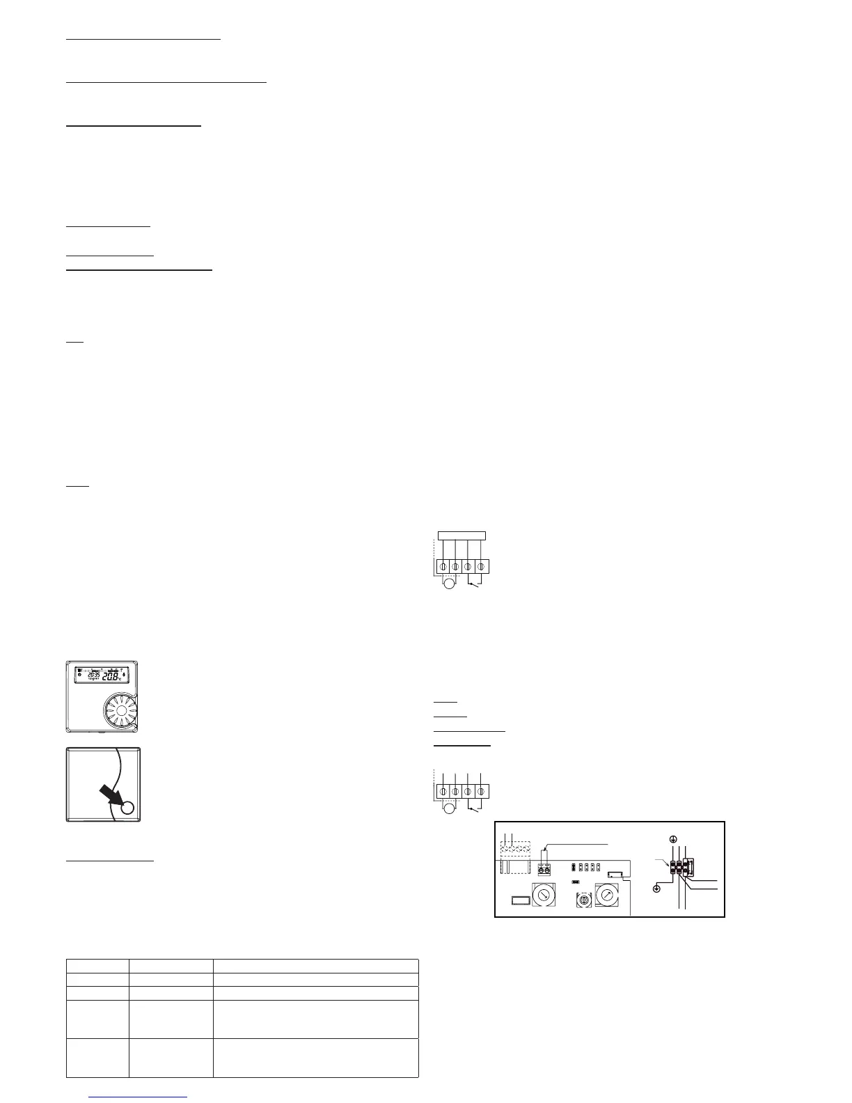
Receiver with spade terminals
Connect the spade terminals from the receiver to the PCB terminals
(room thermostat terminal black & black, open term (OT) bus red
& red (alternative to room thermostat connection), main supply
terminals blue and brown on the main boiler supply socket) - gure
below for a sample boiler connections.
Blue = main supply 230 Vac = neutral N
Brown = main supply 230 Vac = line L
Black & Black = room thermostat = I-O (TA)
Red & Red = OpenTherm = OT bus
See picture for the receiver internal connections.
JP1
JP2
JP3
JP4
JP5
JP6
CN6
CN5
CN12
1
CN13
P1
P3
P2
Remove the bridge
Black RF wires connections
N
L
230 V
M3
F
brown
blue
brown RF
blue RF
IMPORTANT: the link-wire (if tted) must be removed from room
thermostat terminals
IMPORTANT: Secure the receiver wiring harness to the internal boil-
er cable anchors.
INSTALLATION OF RECEIVER
Secure the receiver in the proximity of the boiler using the screws
and wall plugs or using the adhesive magnetic strips on the external
boiler casing including to x (both xing tools are provided).
black
L
N
I
O
black
blue
brown

 Loading...