4
ENGLISH
room and there are no limitations due to ventilation conditions or
room volume.
3 - INSTALLATION REGULATIONS
3.1 Installation regulations
Installationmustbecarriedoutbyqualiedpersonnel.
Alwayscomplywithnationalandlocalregulations.
POSITION
CIAO C.A.I. e: class B appliances cannot be installed in bed-
rooms,bathroomsorshowers,orinroomswithopenueswithout
adequate ventilation. It is imperative that the room in which a gas
appliance is installed has a sufcient inow of air to supply the
quantityofairnecessaryfornormalcombustionandensureproper
ventilation of the room itself. Natural direct ventilation with external
air must be provided for via
- permanent openings in the walls of the room in which the ap-
pliance is installed leading outdoors. These openings must be
madeinsuchawayastoensurethattheoricesonboththe
internal and external side of the wall cannot be obstructed or be
reducedin effectivediameter,theoricesthemselves mustbe
protected with metal grilles or similar means and must be situ-
atednearoorlevelandinalocationthatdoesnotinterferewith
thefunctionoftheue exhaust system (where this position is
not possible, the diameter of the ventilation openings must be
increasedbyatleast50%),
-whilesingleormultiple branchedtheventilationductsmay be
used.
Theventilationairmustbesourceddirectlyfromoutsidethebuild-
ing, away from sources of pollution. Indirect ventilation, with air
drawn from rooms next to the room in which the appliance is in-
stalled,ispermitted,providedthatthelimitationsindicatedbycur-
rent local regulations. The room in which the boiler is to be installed
mustbeadequatelyventilatedincompliancewithapplicableleg-
islation.Detailedprescriptionsfortheinstallationoftheue,gas
piping and ventilation ducting are given in current local regulations.
The aforementioned regulations also prohibit the installation of
electric fans and extractors in the room in which the appliance is
installed.The boiler must have a xed outward leading exhaust
duct with a diameter not smaller than the exhaust hood collar. Be-
forettingtheexhaustoutletconnectortotheue,checkthatthe
uehasadequatedraughtandhasnorestrictionsandthattheex-
haustsofnootherappliancesareconnectedtothesameuepipe.
Whenconnectingtoapre-existinguepipe,checkthatthelatter
isperfectlyclean,asdepositsmaydetachfromthewallofthepipe
duringuseandobstructthepassageoftheuegases,creatinga
situation of severe danger for the user.
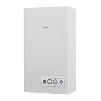
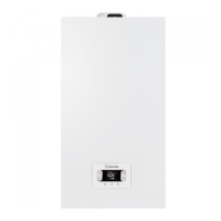
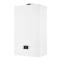
CIAO e canbeinstalledindoors(g.2).
The boiler has protection that guarantees correct operation with a
temperature range from 0°C to 60°C.
To take advantage of protections, the appliance must be able to
startup,sinceanylockoutcondition(forexample,absenceofgas
orelectricalsupply,orsafetyintervention)deactivatestheprotec-
tions.
MINIMUM DISTANCES
In order to have access to the boiler to perform regular mainte-
nance operations, respect the minimum spaces foreseen for instal-
lation(g.3).
For correct appliance positioning:
- do not place it on a cooker or other cooking device
-donotleaveinammableproductsintheroomwheretheboiler
is installed
- heatsensitivewalls(forexample,woodenwalls) mustbepro-
tected with proper insulation.
IMPORTANT
Beforeinstallation,washeverysystempipingcarefullyinorderto
removeany residuesthatmayimpair theoperationofthe appli-
ance.
Under the safety valve, install a water collecting funnel with the
corresponding discharge in the event of leaks due to the overpres-
sureoftheheatingsystem.Thedomestichotwatercircuitdoesnot
needasafetyvalve,butmakesurethatthepressureofwaterworks
does not exceed 6 bar. In case of doubts, install a pressure reducer.
Prior to ignition, make sure that the boiler is designed to operate
withthegasavailable;thiscanbecheckedbythemessageonthe
packagingandtheadhesivelabelindicatingthegastype.
Itisveryimportanttohighlightthatinsomecasesthesmokepipes
are under pressure and therefore, the connections of several ele-
ments must be airtight.
ANTI-FREEZE SYSTEM
Theboileristtedasstandardwithanautomaticanti-freezesys-
temthatactivateswhenthetemperatureofthewaterintheprimary
circuitfallsbelow6°C.Thissystemisalwaysactive,guaranteeing
boiler protection to an outdoor temperature level of -3 °C. To take
advantageofthisprotection(basedonburneroperation),theboiler
mustbeabletoswitchitselfon;anylockoutcondition (e.g.lack
of gas/electricity supply, or safety device intervention) therefore
deactivates the protection. The anti-freeze protection is also ac-
tivewhentheboilerisonstandby.Innormaloperationconditions,
the boiler can protect itself against freezing. If the machine is left
unpoweredforlongperiodsinareaswheretemperaturesmayfall
below0°C,andyoudonotwanttodraintheheatingsystem,you
areadvisedtoaddaspecic,goodqualityanti-freezeliquidtothe
primarycircuit.Carefullyfollowthemanufacturer'sinstructionswith
regardsnotonlythepercentageofanti-freezeliquidtobeusedfor
theminimumtemperatureatwhichyouwanttokeepthemachine
circuit, but also the duration and disposal of the liquid itself.
Forthedomestichotwaterpart,werecommendyoudrainthecir-
cuit.Theboilercomponentmaterialsareresistanttoethylenegly-
col based anti-freeze liquids.
3.2 Securing the boiler to the wall and hydraulic con-
nections
Tofastentheboilertothewall,usethecardboardtemplate(g.
4-5)inthepackaging.Thepositionandsizeofthehydrauliccon-
nections are indicated below:
A CHreturn 3/4”
B CHdelivery 3/4”
C gasconnection 3/4”
D DHWoutput 1/2”
E DHWinput 1/2”
IncaseofreplacementofBerettaboilersfromprevioustype,there
isanadaptationkitofhydraulicconnectionsavailable.
3.3 Electric connection
Theboilersleavethefactorycompletelywiredwiththepowercable
alreadyconnectedandtheyonlyneedtheconnectionoftheroom
thermostat(AT)tobecarriedoutinthespecicterminals.
To access the terminal board:
-turnoffthesystemgeneralswitch
-undothexingscrews(A)oftheshell(g.6)
- move forward and then upwards the shell base to unhook it from
the chassis
-undothexingscrews(B)oftheinstrumentpanel(g.7)
- turn the instrument panel upside down
-removetheterminalboardcover(g.8)
-insertthecableofthepossibleT.A.(g.9)
The room thermostat must be connected as indicated on the wiring
diagram.
Roomthermostatinputinsafetylowvoltage(24Vdc).
Theconnectiontothemainssupplymustbecarriedoutthrougha
separationdevicewithanomnipolaropeningofatleast3.5mm(EN
60335-1,categoryIII).
The appliance operates with an alternating current of 230 Volt/50
Hzandanelectricalpowerof85Wfor24-28C.A.I.-100Wfor24
C.S.I.-125Wfor 28 C.S.I. (and complies with thestandardEN
60335-1).
Itiscompulsorytocarryoutconnectionwithanefcientearth
circuit, according to national and local legislation.
Itisadvisabletocomplywithneutralphaseconnection(L-N).
The earth wire must be a couple of centimetres longer than
the others.
Do not use gas and/or water pipes to earth electrical appliance.
Themanufacturerdeclinesliabilityforanydamageiftheappliance
was not connected to an earth circuit.
 Loading...