CIAO e
7
4.3 Switching off
Temporary switching off
In case of absence for short periods of time, set the mode selector
(3-g.1a)to
(OFF).
Inthisway(leavingtheelectricityandfuelsuppliesenabled),the
boilerisprotectedbythefollowingsystems:
- Anti-frost device: when the temperature of the water in the boiler
fallsbelow5°C,thecirculatorand,ifnecessary,theburnerare
activated at minimum output levels to bring the water tempera-
turebacktothevaluesforsafety (35°C). During the anti-frost
cycle,thesymbol
appears on the digital monitor.
-Circulatoranti-blockingfunction:anoperationcycleisactivated
every24hours.
Long period switching off
In case of absence for long periods of time, set the mode selector
(3-g.1a)to
(OFF).
Then,closethegastappresentonthesystem.Inthiscase,anti-frost
deviceisdeactivated:emptythesystems,incaseofriskoffrost.
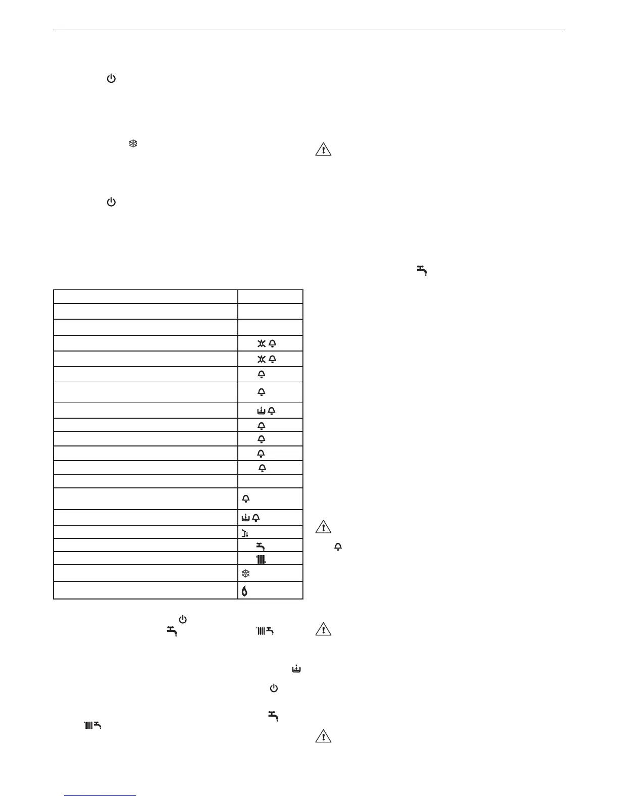
4.4 Light signals and faults
Theoperatingstatusoftheboilerisshownonthedigitaldisplay,
belowisalistofthetypesofdisplays.
To restore operation (deactivate alarms):
BOILER STATUS DISPLAY
Stand-by -
OFF status OFF
ACF module lockout alarm
A01
ACF electrical fault alarm
A01
Limit thermostat alarm
A02
Airpressureswitchalarm(C.S.I.models)
Fumes thermostat (C.A.I.models)
A03
H2O pressure switch alarm
A04
NTC domestic water fault A06
NTC heating fault
A07
Parasiteame
A11
Electric calibration min and max heating
ADJ
Transient awaiting ignition 88
°C
ashing
Airpressureswitchintervention(C.S.I.models)
Fumes thermostat intervention(C.A.I.models)
ashing
H2O pressure switch intervention
ashing
External probe present
Domestic water heat request 60
°C
Heating heat request 80
°C
Anti-freeze heat request
Flame present
Faults A 01-02-03
Position the function selector to
(OFF),wait5-6secondsthen
set it to the required position
(summermode)or (winter
mode).Iftheresetattemptsdonotreactivatetheboiler,contactthe
Technical Assistance Centre.
Fault A 04
Inadditiontothefaultcode,thedigitaldisplayshowsthesymbol
.
Checkthepressurevalueindicatedbythewatergauge:
if it is less than 0.3 bar, position the function selector to
(OFF)
andadjust the lling tap (L g. 13) until thepressurereaches a
value between 1 and 1.5 bar.
Then position the mode selector to the desired position
(sum-
mer)or
(winter).
If pressure drops are frequent, request the intervention of the Tech-
nical Assistance Service.
Fault A 06
Theboileroperatesnormallybutcannotreliably maintainacon-
stant domestic hot water temperature, which remains set at around
50°C. Contact the Technical Assistance Centre.
Fault A 07
Contact the Technical Assistance Centre.
4.5 Adjustments
Theboilerhasalreadybeenadjustedbythemanufacturer.
Ifitisnecessarytoadjustitagain,forexampleafterextraordinary
maintenance, after replacement of gas valve or after gas conver-
sion,carryoutthefollowingprocedure.
The maximum output adjustment must be carried out in the
sequenceindicatedexclusivelybyqualiedpersonnel.
- removetheshellunscrewingthexingscrewsA(g.6)
- unscrewbytwoturnsthescrewofthepressuretestpointdown-
stream the gas valve and connecting the pressure gauge
- disconnect the compensation inlet of the air distribution box
(onlyC.S.I.model)
4.5.1 Maximum power and minimum domestic hot wa-
ter adjustment
- Fullyopenthehotwatertap
- on the control panel:
- set the mode selector to
(summer)(g.2a)
- turn the domestic hot water temperature selector to its maximum
(g.7a)
- powertheboilersettingthesystemmainswitchto“on”
- check that the pressure on the pressure gauge is stable; or with
a milliammeter in series to the modulator, make sure that the
modulatorsuppliesthemaximumavailablecurrent(120mAfor
G20and165mAforLPG).
- carefullypriseouttheprotectioncapoftheadjustmentscrews,
usingascrewdriver(g.15)
- with a fork spanner CH10 use the adjustment nut of the maxi-
mum output in order to obtain the value indicated in table "Tech-
nical data"
- disconnect the modulator faston
- wait until the pressure on the pressure gauge is stable at mini-
mum value
- paying attention not to press the internal shaft, use anAllen
spanner to turn the red adjustment screw for domestic hot water
minimum temperature regulation, calibrating it until the pressure
gauge reads the value indicated in the table "Technical data"
- reconnect the modulator faston
- close the domestic hot water tap
- carefullyrettheprotectioncapoftheadjustmentscrews.
4.5.2 Minimum and maximum heating electric adjust-
ment
The “electric adjustment” function is activated and deacti-
vatedexclusivelybythejumper(JP1)(g.16).
ADJ
appearsonthedisplaytoindicatethatthecalibrationpro-
cedureisunderway.
Thefunctioncanbeenabledinthefollowingway:
- bypoweringthecardwiththejumperJP1insertedandthemode
selectorinwinterposition,independentlyfromthepossiblepres-
ence of other operation request.
- byinsertingthejumperJP1,withthe mode selector in winter
position, without heat request in progress.
Byactivatingthefunctiontheburnerisignitedthroughsimu-
lation of heat request in heating.
To perform calibration operations, proceed as follow:
- switch off the boiler
- remove the shell and access the card
-insertthejumperJP1(g.16)toenabletheknobsplacedonthe
control panel to the minimum and maximum heating adjustment
functions.
- makesurethatthemodeselectorisinwinterposition(seesec-
tion4.2).
- power the boiler
Electric card in voltage (230 Volt)
-turntheheatingwatertemperatureadjustmentknobB(g.17)
until it reaches the minimum heating value as indicated in the
multigas table
 Loading...