6
ENGLISH
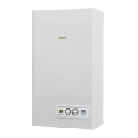
C12-C12xDischargeviaconcentricwalloutlet.Thepipesmayleavethe
boilerindependently, butthe outlets mustbe concentric orsufciently
closetogethertobesubjectedtosimilarwindconditions(within50cm)
C22 Dischargeviaconcentricoutletincommonsmokepipe(suctionand
dischargeinthesamepipe)
C32-C32x Discharge via concentric roof outlet. Outlets as for C13
C42-C42x Discharge and suction in common separate smoke pipes, but
subjected to similar wind conditions
C52-C52x Separate discharge and suction lines on wall or roof and in ar-
eas with different pressures. The discharge and suction lines must never
Rear outlet
3.5 Fumes exhaustion and air suction (CIAO C.A.I. e)
Observeapplicablelegislationregardinguegasexhaustion.
Theexhaustsystemmustbemadeusingrigidducting,thejoints
betweenelementsmustbehermeticallysealedandallcomponents
must be resistant to heat, condensation and mechanical stress and
vibration.
Non insulated outlet pipes are potential sources of danger.
The apertures for the combustion air must be realised in compli-
ance with applicable legislation. If condensation forms, the exhaust
duct must be insulated. Figure 12 shows a top-down view of the
boilerwiththedimensionsfortheuegasexhaustoutlet.
Flue gas safety system
Theboilerfeaturesasystemmonitoringthatuegasesarecor-
rectlyexhausted which arreststhe boiler inthe event of a fault:
uegasthermostat,g.11b.Torestorenormaloperation,turnthe
function selector to
(3g.1a),waitafewseconds,thenturnthe
function selector into the desired position.
If the fault persists, call a qualied technical from theTechnical
SupportService.Theuegasexhaustionmonitoringsystemmust
neverbebypassedorrenderedinoperable.Useonlyoriginalre-
placementpartswhenreplacingthewholesystemorfaultysystem
components.
3.6 Filling the heating system (g. 13)
Oncethehydraulicconnectionshavebeencarriedout,lltheheat-
ingsystem.Thisoperationmustbecarriedoutwithcoldsystem
following this instructions:
-turnbytwoorthreeturnstheautomaticreliefvalvecap(I)
- make sure the cold water inlet tap is open
-turnonthellingtap(Lg.13)untilthepressureindicatedbythe
water pressure gauge is between 1 and 1.5 bar.
Oncellingiscomplete,closethellingtap.
Theboilerhasanefcientairseparatorsonomanualintervention
isneeded.The burner switches on only if the air reliefphaseis
nished.
3.7 Emptying the heating system
Toemptythesystem,proceedasfollow:
- switch off the boiler
- loosetheboileroutlettap(M)
- emptythelowestpointsofthesystem.
3.8 Emptying the domestic hot water
Whenthereisriskoffrost,thedomestichotwatersystemmustbe
emptiedinthefollowingway:
- close the main tap of the water mains
- open all the hot and cold water taps
-emptythelowestpoints.
WARNING
Whencarryingoutthedischargeofthesafetyvalve(N),itmustbe
connectedtoasuitablecollectionsystem.Themanufacturerisnot
responsibleforpossibledamagesduetosafetyvalveoperation.
4 - IGNITION AND OPERATION
4.1 Preliminary checks
Firstignitioniscarriedoutbycompetentpersonnelfromanautho-
rised Technical Assistance Service Beretta.
Before starting up the boiler, check:
a) thatthesupplynetworksdata(electric,water,gas)corresponds
to the label data
b) thatpipingleavingtheboileriscoveredbythermalinsulation
sheath
c) thatuegasextractionandairsuctionpipesworkcorrectly
d) thatconditionsforregularmaintenanceareguaranteedifthe
boiler is placed inside or between furniture
e) thesealofthefueladductionsystem
f) thatfuelcapacitycorrespondstovaluesrequestedbytheboiler
g) thatthefuelsupplysystemhasthecorrectcapacityforthenec-
essarycapacitytotheboilerandthatithasallthesafetyand
controldevicesprescribedbycurrentregulations.
4.2 Appliance ignition
Tostart-uptheboileritisnecessarytocarryoutthefollowingop-
erations:
- power the boiler
- openthegastappresentinthesystemtoallowfuelow
- turnthemodeselector(3-g.1a)tothedesiredposition:
Summer mode:turningtheselectortothesymbolsummer
(g.
2a)thetraditionalfunctionofonlydomestichotwaterisactivated.If
thereisadomestichotwaterrequestthedigitaldisplayshowsthe
hotwatersystemtemperature,theicontoindicatethehotwater
supplyandtheameicon
Winter mode:byturningthemodeselectorwithintheareamarked
+and-(g.2b),theboilerprovidesdomestichotwaterandheat-
ing. If there is a heat request, the boiler switches on and the digital
monitor indicates the heating water temperature, the icon to indi-
cateheatingandtheameicon(g.3a).Ifthereisadomestichot
waterrequest,theboilerswitchesonandthedigitaldisplayshows
thehotwatersystemtemperature,theicontoindicatethehotwa-
tersupplyandtheameicon(g.4a)
Adjustment of domestic hot water temperature
Toadjustdomesticwatertemperature(bathrooms,showers,kitch-
en,etc.), turn the knobwith symbol
(g. 2b) within thearea
marked + and -.
Theboilerisstandbystatusuntil,afteraheatrequest,theburner
switcheson and the digital display shows thehot water system
temperature, the icon to indicate the hot water supply and the
ameicon.
The boiler will be in function until the adjusted temperature is
reached,afterwardsitwillbein“standby”again.
Environment Automatic Adjustment System Function
(S.A.R.A.) g. 6a
By setting the heating water temperature selector to the area
marked by AUTO - temperature value from 55 to 65°C - the
S.A.R.A.self-adjusting system isactivated: the boilervaries the
deliverytemperatureaccordingtotheclosingsignaloftheroom
thermostat. When the temperature set with the heating water tem-
perature selector is reached, a 20 minutes count begins. If during
this period the room thermostat still requests heat, the value of the
settemperatureautomaticallyincreasesby5°C.
When the new value is reached, other 20 minutes count begins.
If during this period the room thermostat still requests heat, the
valueofthesettemperatureautomaticallyincreasesby5°C.
This new temperature value is the result of the temperature set
manuallywiththeheatingwatertemperatureselectorandthein-
crease of +10 °C of the S.A.R.A function.
After the second increasing cycle, the temperature value is re-
storedtothevaluesetbytheuserandtheabovementionedcycle
isrepeateduntiltheambientthermostatrequestisfullled.
be positioned on opposite
walls
C62-C62x Discharge and
suction lines using pipes
marketedandcertiedsep-
arately(1856/1)
C82-C82x Discharge via sin-
gle or common smoke pipe
and wall suction line
C92-C92x Discharge on
roof(similartoC33)andair
suction from a single exist-
ing smoke pipe
C52
C32
C32
C92
C82
C22
C22 C42
C42
C12
C12C52
MAX 50 cm
 Loading...