Blu=Blue / Marrone=Brown / Nero=Black / Rosso=Red/ Bianco=White / Viola=Violet /
Grigio=Grey /
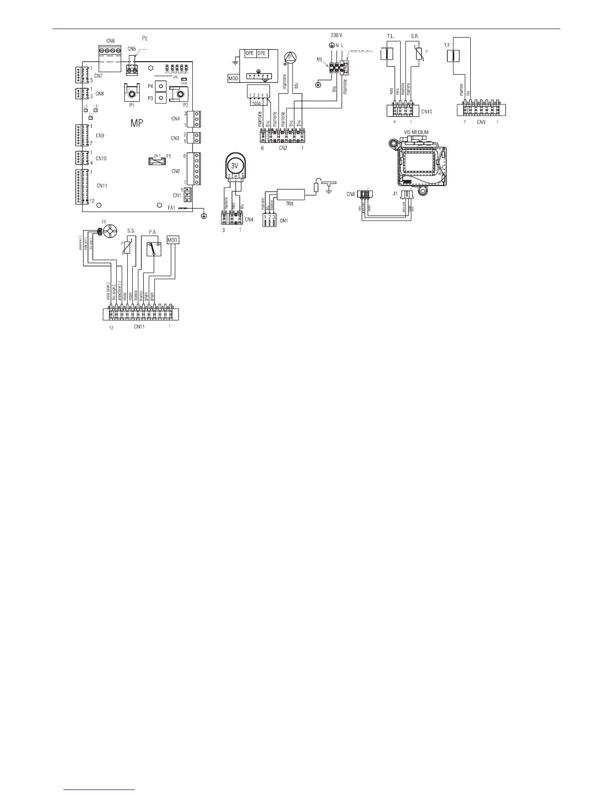
A = 24V Low voltage ambient thermostat jumper
B = Gas valve
C = I/D electrode
D = Fuse 3.15A F
MP Control board
P1 Potentiometer to select off - summer - winter – reset / temperature
heating
P2 Potentiometer to select domestic hot water set point
P3 Potentiometer to select temperature regulation curve
P4 Solar function potentiometer (not used)
JP1 Bridge to enable knobs for calibration
JP2 Bridge to reset the heating timer and log maximum electrical heating in calibration
JP3 Bridge to select MTN - LPG
JP4 Absolute domestic hot water thermostat selector
JP5 Bridge to select heating operation only (not used)
JP6 Flow meter management enabling (not used)
LED Led 1 (green) to indicate operation status or temporary stop
Led 2 (yellow) to indicate preheating is ON (not used)
Led 3 (red) to indicate permanent lockout status
CN1÷CN12
Connectors (CN4 not used)
F1 Fuse 2A T
F External fuse 3.15A F
M3 Terminal board for external connections
T.A. Ambient thermostat
I./D.E. Ignition/Detection electrode
TRX Remote ignition transformer
T.F. Flue gas thermostat
S.R. Primary circuit temperature probe (NTC)
T.L. Limit thermostat
OPE Gas valve operator
P Pump
S.S. Domestic hot water circuit temperature probe (NTC)
PA Heating pressure switch (water)
MOD Modulator
3V 3-way servomotor valve
FS Domestic hot water ow meter
Bleu=Blue / Marron=Brown / Noir=Black / Rouge=Red / Blanc=White / Violet=Violet /
Gris=Grey /
A = Jumper du thermostat dans un environnement de 24V
B = Soupape gaz
C = Électrode A/R
D = Fusible 3.15A F
MP Carte de commande
P1 Potentiomètre de sélection off - été - hiver – réarmement/température
chauffage
P2 Potentiomètre de sélection point de consigne sélection point de consigne sanitaire
P3 Potentiomètre de sélection courbes de régulation thermique
P4 Potentiomètre de fonction solaire (non utilisé)
JP1 Shunt activation poignées au réglage
JP2 Shunt mise à zéro minuterie chauffage et mémorisation du chauffage électrique maximum en réglage
JP3 Shunt sélection MTN - GPL
JP4 Sélecteur des thermostats absolus sanitaire
JP5 Shunt sélection fonctionnement uniquement chauffage (non utilisé)
JP6 Activation de la gestion du uxmètre (non utilisé)
LED Led 1 (verte) signalisation de l'état fonctionnement ou arrêt provisoire
LED 2 (jaune) signalisation de préchauffage ON (non utilisé)
LED 3 (rouge) signalisation état de blocage dénitif
CN1÷CN12
Connecteurs de branchement (CN4 non utilisé)
F1 Fusible 2A T
F Fusible externe 3.15A F
M3 Bornier pour branchements externes
T.A. Thermostat d'ambiance
E.A./R. Électrode d'allumage/détection
TRX Transformateur d'allumage à distance
T.F. Thermostat fumées
S.R. Sonde (NTC) de température du circuit primaire
T.L. Thermostat limite
OPE Opérateur soupape gaz
P Pompe
S.S. Sonde (NTC) de température du circuit sanitaire
PA Pressostat chauffage (eau)
MOD Modulateur
3V Servomoteur de la vanne a 3 voies
FS Débitmètre sanitaire
A
B
D
C

 Loading...