Electrical 8
Connection Procedure:
Step 1. Connect the ground wire first as shown in Figure 6. The ground
wire must be a solid copper wire at least as large as the power sup-
ply wires.
Step 2. There must be a solid metal connection between the pressure
switch and the motor for motor grounding protection. If the pres-
sure switch is not connected to the motor, connect the green
ground screw in the switch to the green ground screw under the
motor end cover. Use a solid copper wire at least as large as the
power supply wires.
Step 3. Connect the ground wire to a grounded lead in a service panel, to a
metal underground water pipe, to a metal well casing at least ten
feet (3M) long, or to a ground electrode provided by the power
company or the hydro authority.
Step 4. Connect the power supply wires to the pressure switch as shown in
Figure 6.
You have just completed the wiring for your pump.
Please go to Page 9 for startup preparations.
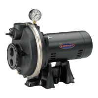
Wiring Chart – Recommended Wire and Fuse Sizes
Branch
DISTANCE IN FEET(METERS) FROM MOTOR TO SUPPLY
Max. Fuse
0 - 100 101 - 200 201 - 300 301 - 400 401 - 500
Motor Load Rating
(0 - 30) (31 - 61) (62 - 91) (92 - 122) (123 - 152)
Series HP Volts Amp Amp AWG WIRE SIZE (mm
2
)
5HN 1/2 115/230 12.2/6.1 20/15 12/14(3/2) 10/14(5.5/2) 8/14(8.4/2) 6/12(14/3) 6/12(14/3)
7HN 3/4 115/230 14.8/7.4 20/15 12/14(3/2) 8/14(8.4/2) 6/14(14/2) 6/12(14/3) 4/10(21/5.5)
10HN 1 115/230 19.2/9.6 25/15 10/14(5.5/2) 8/14(8.4/2) 6/12(14/3) 4/10(21/5.5) 4/10(21/5.5)
5SN 1/2 115/230 8.8/4.4 15/15 14/14(2/2) 12/14(3/2) 10/14(5.5/2) 8/14(8.4/2) 8/12(8.4/3)
7SN 3/4 115/230 12.2/6.1 20/15 12/14(3/2) 10/14(5.5/2) 8/14(8.4/2) 6/12(14/3) 6/12(14/3)