8
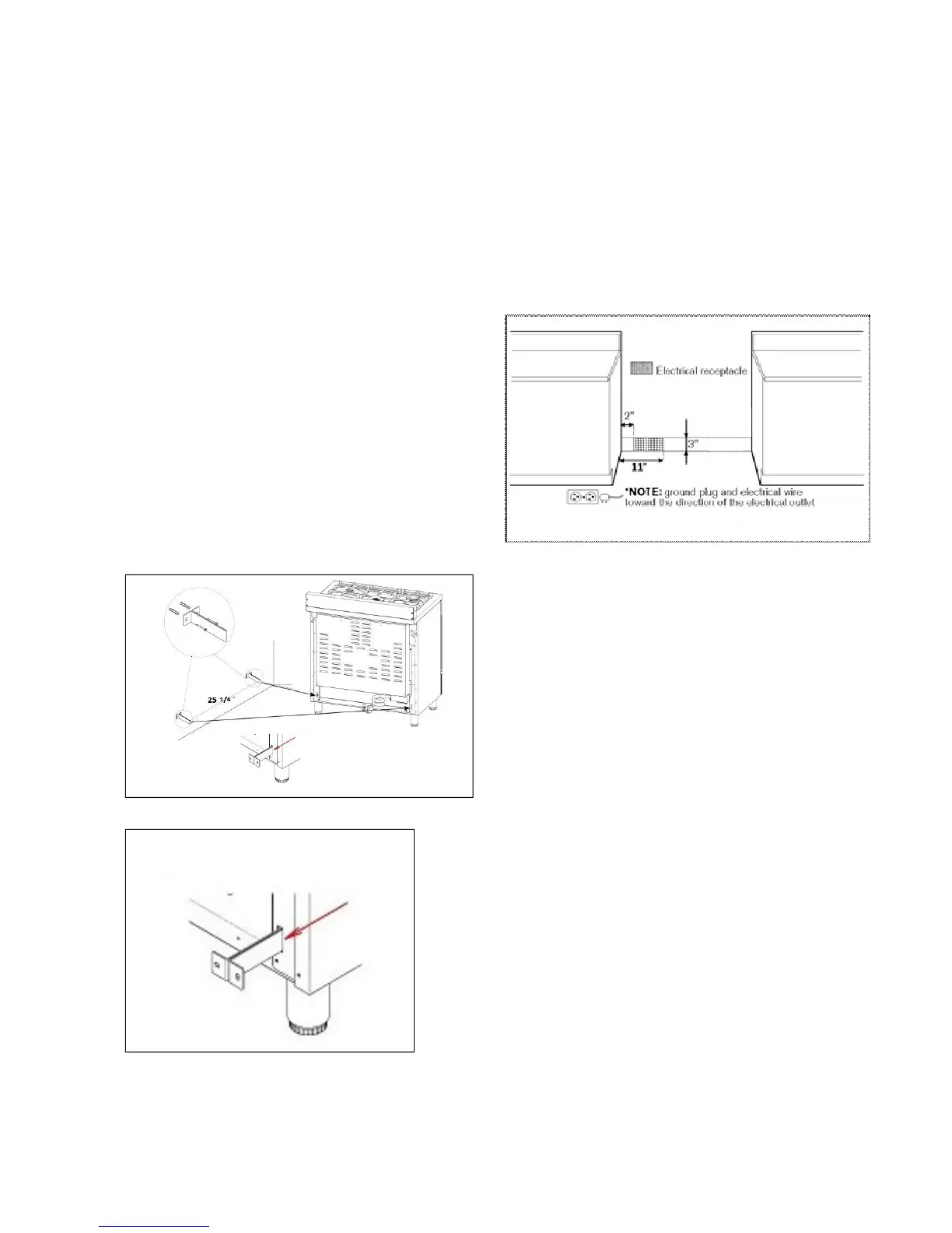
INSTALLINGTHEANTI‐TIPStability
DEVICE
Theanti‐tipbracketshippedwiththerangemust
beproperly secured to the rearwallas shown in
thepicturebelow.
Theheightof thebracketfromthefloormustbe
determined after the range legs have been
adjusted to the desired height and afterthe
rangehasbeenlevelled.
Measure the distance from the floor to the
bottom of the anti‐tip bracket receptacle on the
backoftheappliance.
Position the two anti‐tip brackets on the wall at
the desired height plus 1/8" (0.32 cm). The
bracketsmustbeplacedat2”5/16 (6,0cm)from
the side
of the range. The distance between the
twobracketis25”1/4(64,1cm).
Secure the brackets to the wall with appropriate
hardware.
Slidetherangeagainstthewalluntilthebrackets
are fully inserted into their receptacles on the
backoftherange.
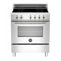
INSTALLATIONREQUIREMENTS
ELECTRICAL
A properly grounded and horizontally‐mounted
electrical receptacle Type NEMA 14‐50R should
beinstallednohigherthan3"(7.6cm)abovethe
floor, no less than 2” (5 cm) and no more than
11” (28 cm) from the left side (facing product);
refer to ELECTRICAL CONNECTION section pag.
12.
Checkalllocalcoderequirements.