Do you have a question about the Berthoud COSMOS 18 PRO and is the answer not in the manual?
Separate the fixing elements on the rod to the maximum.
Place lever n°3 on the outside of beam n°1, aligning edges and holes.
Insert screw n°4 through the beam for right-handed use.
Attach washers n°5, n°6 and nut n°7 to screw n°4, tighten nut.
Place lever n°3 on the cap side of the tank, lining up edges and holes.
Insert 2 screws n°4 into the beam.
Place washers n°5, n°6 and nuts n°7 around screws n°4, tighten nuts.
Insert mixer tap n°9 into the tank and clip onto the hollow grooves.
Slide sealing ring n°17 onto hose n°10, ensuring correct orientation.
Attach hose n°10 onto connector n°19, twisting for easier fit.
Push sealing ring n°17 or clip n°18 down until it reaches the piston.
Hold the ring and pull the hose to verify the connection.
Slide lance tube n°11 into part n°13.
Dismantle nuts from nozzle holder n°12 and handle n°10.
Fit nuts from n°12 and n°10 onto rod n°11.
Insert rod n°11 into handle n°10 and nozzle unit n°12, tighten nuts.
Lay straps flat with adjusters underneath, slide central part into slot.
Insert part n°15 into loop and pull strap to lock.
Slide small strap loops into the lateral slots on the sprayer.
Insert part n°16 into each strap loop, then pull strap to lock.
Adjust strap length using the strap adjusters as per requirements.
Vertically slide part n°13 into the T notch.
| Brand | Berthoud |
|---|---|
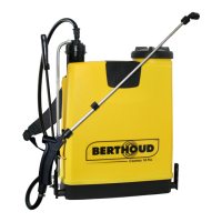
| Model | COSMOS 18 PRO |
| Category | Paint Sprayer |
| Language | English |