2
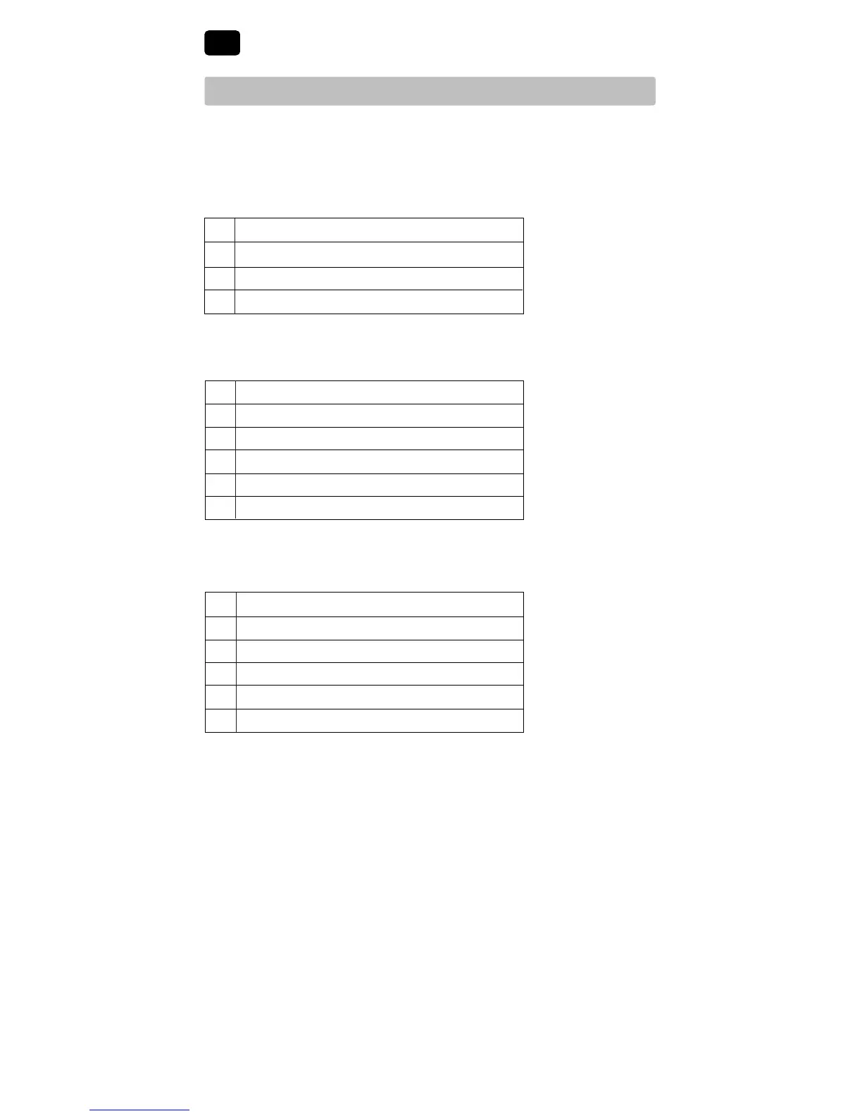
Connect Your Wires
3
Heat Only or Millivolt
Set Installer Switch to NORM
Rh*
PowerConnection
W HeatRelay(appearsasW1/EonBT21NP)
G FanRelay[note 4]
C 24VoltACTransformerCommon[note 1]
1 HEAT / 1 COOL Single or Dual Transformer
Set Installer Switch to NORM
Rh*
24VoltACPower(heatingtransformer)[note 2]
Rc*
24VoltACPower(coolingtransformer)[note 2]
W HeatRelay(appearsasW1/EonBT21NP)
Y CompressorRelay(appearsasY1onBT21NP)
G FanRelay
C 24VoltACTransformerCommon[note 1, 3]
Typical Wiring Configurations
NOTE: The “Installer Switch” option will be configured in the next step.
Conventional Systems
*AppearsasRonBT21NP(singletransformer)
NOTES - Conventional Systems
[1]Ifbatteriesareinstalledthe24VoltACcommonconnectionisoptional
[2]Removefactoryinstalledjumperfordualtransformersystems
[3]Indualtransformersystems,transformercommonmustcomefrom
coolingtransformer
[4]Ifneededforsystem
Provide disconnect and overload protection as required.
2 HEAT / 1 COOL Single Transformer (BT21NP Only)
Set System Type to NORM
R
24VoltACPower
W1 HeatRelayStage1
W2 HeatRelayStage2
Y1 CompressorRelayStage1
G FanRelay
C 24VoltACTransformerCommon[note 1]